
Metal 3D Printing (SLM) – 316L, AlSi10Mg, ±0.02 mm
Technical summary: CT3D provides metal 3D printing in Vietnam using Selective Laser Melting (SLM) on German-standard machines, focusing on two main material families: steels (316L and 304L stainless, 17-4PH, H13 tool steel, Maraging 18Ni300) and aluminum alloys (AlSi10Mg, AlSi12, AlSi7Mg, Scalmalloy). Tolerances reach ±0.02 mm, as-printed surface roughness is 6–10 µm, and the 250×250×300 mm build volume can be extended with modular assembly. We accept orders from a single part, with post-processing including stress relieving, CNC machining of mating faces, bead blasting, polishing and plating.
Metal additive manufacturing makes sense when a part has internal channels, lattices or consolidated features that machining cannot reach, or when a replacement part is needed in a quantity of one. Send a STEP file (preferred) or STL with a 2D drawing of critical tolerances; every quote includes a free manufacturability (DFM/DfAM) review, and we sign an NDA on request.
Metal SLM at a glance
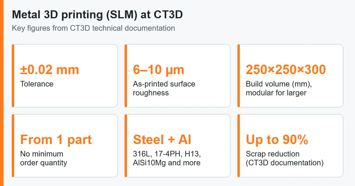
| Process | Selective Laser Melting (SLM), German-standard machines |
|---|---|
| Tolerance | ±0.02 mm |
| As-printed roughness | 6–10 µm |
| Build volume | 250×250×300 mm; larger parts by modular assembly |
| Main alloys | 316L, 304L, 17-4PH, H13, Maraging 18Ni300, AlSi10Mg, AlSi12, AlSi7Mg, Scalmalloy |
| Other metals | Titanium, copper, Inconel, Hastelloy, CoCr |
| Minimum order | From 1 part |
| Pricing | Quoted per file |
How SLM works and how it differs from subtractive machining
Inside a sealed build chamber filled with shielding gas, a thin layer of metal powder is spread evenly across the build plate. A laser beam scans the part’s cross-section for that layer, fully melting the powder particles so they solidify into dense metal. The build plate lowers, a fresh layer of powder is spread, and the process repeats until the part is complete. Because material is only added where it is needed, internal geometries such as curved channels, lattice structures and hollow walls can be produced in a single build – something 3-, 4- or 5-axis CNC milling cannot achieve because the tool cannot reach them. According to CT3D documentation, the tensile properties of SLM parts are equivalent to or 10–15% higher than cast parts, scrap is reduced by up to 90%, and the cost of importing spare parts can be cut by up to 40%.
- Powder spreading: a recoater lays a thin, even layer of metal powder on the build plate.
- Laser melting: the laser fully melts the powder along the part’s cross-section and its supports.
- Layer repetition: the plate lowers and the cycle repeats until the part is complete.
- Depowdering and stress relief: loose powder is recovered and the part is stress relieved while still on the plate.
- Post-processing: separation, support removal, blasting, machining and finishing to the drawing.
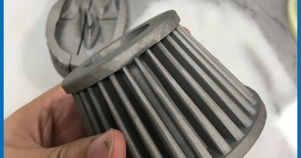
Technical specifications
| Parameter | Value | Application notes |
|---|---|---|
| Technology | SLM, German-standard machines | Full melting of metal powder |
| Tolerance | ±0.02 mm | Leave machining stock on precision mating faces for CNC |
| As-printed surface roughness | 6–10 µm | Further reduced by bead blasting and polishing |
| Build volume | 250×250×300 mm | Larger parts: modular assembly |
| Minimum order quantity (MOQ) | From 1 part | Ideal for prototypes and replacement parts |
| Post-processing | Stress relieving, CNC of mating faces, bead blasting, polishing, plating | Selected according to functional requirements |
| Pricing | Quoted per file | Depends on volume, build height, material and post-processing |
Source: CT3D metal 3D printing specification documents.
Materials & standards: steel and aluminum
Stainless steels and tool steels
316L stainless steel is low in carbon and contains molybdenum, offering excellent corrosion resistance and good printability; it is commonly used for parts in contact with water, chemicals and food-processing equipment. 304L is the economical choice for less aggressive environments. 17-4PH is a precipitation-hardening steel that can be heat treated for higher hardness and strength in shafts, small gears and load-bearing parts. H13 and Maraging 18Ni300 are tool steels used for injection mold inserts and die-casting tooling with conformal cooling channels. For more depth, see our articles on 316L stainless steel 3D printing and conformal-cooled mold inserts.
Aluminum alloys
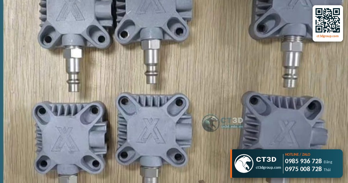
AlSi10Mg is the most widely printed aluminum alloy: lightweight, thermally conductive and with a high strength-to-weight ratio, it suits heat sinks, brackets, device housings, and automotive and drone components. AlSi12 has good flowability and suits thin walls. AlSi7Mg is close to traditional casting alloys. Scalmalloy is a high-strength aluminum alloy for demanding lightweight structures. Aluminum parts are usually heat treated after printing to stabilize their mechanical properties. See also our article on AlSi10Mg aluminum 3D printing.
| Material | Key properties | Typical applications |
|---|---|---|
| 316L / 304L | Corrosion resistant, ductile | Valves, nozzles, food-grade and marine parts |
| 17-4PH | Heat-treatable for hardness | Load-bearing mechanical parts, tooling |
| H13 / Maraging 18Ni300 | Heat resistant, fatigue resistant, high hardness | Mold inserts, mold cores with cooling channels |
| AlSi10Mg / AlSi12 | Lightweight, thermally conductive | Heat sinks, housings, lightweight brackets |
| Scalmalloy | High-strength aluminum | Weight-optimized structures |
Material list per CT3D documentation; in addition to steel and aluminum, CT3D also prints titanium, copper, Inconel, Hastelloy and CoCr.
Not sure which alloy fits? Tell us the operating temperature, the medium the part touches (water, oil, chemicals, food), the loads and whether weight matters. Those four answers usually narrow the choice to one or two alloys.
Design for metal additive manufacturing (DfAM)
A part designed for CNC milling is not necessarily optimized for SLM. Downward-facing surfaces angled below roughly 45° from the build plate usually need supports, and metal supports must be removed by wire EDM or machining. Large horizontal holes should be changed to a teardrop profile so they are self-supporting. Walls that are too thin are prone to distortion from thermal stress. Enclosed cavities need drain holes so excess powder can be removed. Our guide to design for metal 3D printing (DfAM) covers these rules in more detail.
| Feature | Guideline (typical industry values – confirmed per part in the DfAM review) |
|---|---|
| Overhangs | Surfaces below roughly 45° from the plate need supports; redesign as chamfers where possible. |
| Horizontal holes | Small holes typically print without supports; larger ones should use a teardrop or diamond profile. |
| Wall thickness | Typically 0.5–1 mm minimum, thicker for tall unsupported walls to limit thermal distortion. |
| Internal channels | Smooth, curved paths without sharp corners; diameter large enough to clear powder. |
| Powder drain holes | At least one, ideally two, per enclosed cavity so powder can be blown and vibrated out. |
| Machining allowance | Leave stock, typically a few tenths of a millimeter, on mating faces, bores and sealing surfaces that will be CNC finished. |
| Threads | Small or precision threads are best tapped or machined after printing. |
| Part consolidation | Combine assemblies into one printed part where it removes joints, seals or fasteners. |
Post-processing and surface finishes
After printing, the part is still attached to the build plate and carries residual stress. The typical post-processing sequence is stress relieving while still on the plate, part separation, support removal, bead blasting for a uniform surface, CNC machining of mating faces and threaded holes to GD&T tolerances, then polishing or plating if required. See also our article on post-processing metal printed parts.

| Finish | What it does | Best for |
|---|---|---|
| As-built (6–10 µm) | Supports removed, surface left as printed | Internal parts, functional tests |
| Bead blasted | Uniform matte surface, removes loose particles | Most functional parts |
| CNC machined faces | Brings mating faces, bores and threads to drawing tolerances | Assemblies, sealing faces, bearing seats |
| Polished | Smoother, brighter surface | Visible parts, flow surfaces |
| Plated | Adds a surface coating for appearance or protection | Decorative or exposed parts |
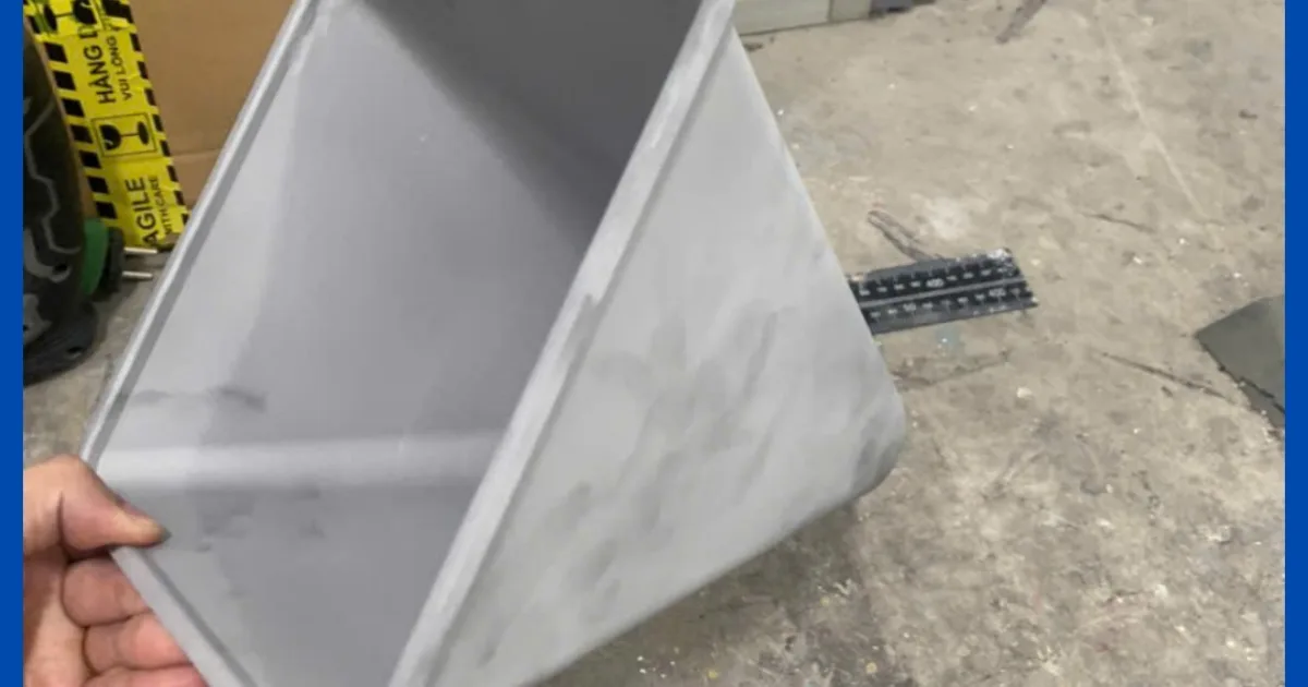
Industry applications
- Tooling and molds: injection mold inserts with conformal cooling channels for uniform cooling – see also 3D printed molds and rapid tooling.
- Plant maintenance: discontinued replacement parts, combined with 3D scanning and reverse engineering.
- Automotive, motorcycle and drone: lightweight aluminum brackets, manifolds and test parts.
- Electronics and energy: lattice heat sinks and liquid cooling blocks.
- Food and chemical equipment: nozzles, valves and stainless steel parts with complex internal channels.
Metal 3D printing vs CNC machining vs casting
To decide whether to print or machine a part, read our comparison of metal 3D printing vs CNC machining, or see our CNC machining services. The table below summarizes the general trade-offs; the right answer often combines SLM for the complex body with machining for the precision faces.
| Criterion | SLM metal 3D printing | CNC machining | Casting |
|---|---|---|---|
| Internal channels, lattices | Yes, in one build | Limited by tool access | Possible with cores, at tooling cost |
| Tooling | None | None (fixtures only) | Pattern and mold required |
| Economic quantity | 1 to small batches | 1 to medium batches | Medium to large batches |
| Material use | Near-net shape; CT3D documentation cites up to 90% less scrap | Material removed as chips | Near-net shape plus gates and risers |
| Strength | Equivalent to or 10–15% above cast parts (CT3D documentation) | Wrought material properties | Cast properties |
| Precision faces | ±0.02 mm; critical faces machined | Excellent | Machining required |
| Size | 250×250×300 mm per build, modular beyond | Machine-dependent | Large parts possible |

Quality control
The quality of an SLM part depends on the powder, laser parameters, build orientation and heat treatment. CT3D controls this by using validated parameter sets for each material, recording part orientation and position on the build plate, stress relieving before separation, and measuring critical dimensions. For assembly parts, functional surfaces are CNC machined rather than left as-printed. On request, we can 3D scan the part and produce a deviation map against CAD – see 3D scanning inspection; for internal channels and porosity checks, see industrial CT inspection.
| Risk | Cause | Countermeasure |
|---|---|---|
| Warping after removal from the plate | Residual thermal stress | Stress relieving before separation |
| Rough down-facing surfaces | Support contact surfaces | Reorient the build, machine or polish |
| Powder trapped in channels | Missing drain holes | Add drain holes, blow-out and vibration cleaning |
| Out-of-tolerance mating faces | Thermal shrinkage | Leave machining stock, finish by CNC |

How to order: our workflow
- RFQ: send a STEP file (preferred) or STL, together with a 2D drawing with tolerances, material, quantity and operating environment.
- DFM review: our engineers check printability and recommend build orientation, support areas and machining allowances, and adjust the geometry for DfAM if permitted.
- Quote: quoted per file, covering printing, heat treatment, machining, surface finishing and lead time.
- Production: SLM printing, stress relieving, part separation and post-processing as required.
- QC: inspection of critical dimensions, appearance, threads and fit; 3D scanning against CAD is available.
- Delivery: door-to-door delivery throughout Vietnam or collection from our workshop; international shipping can be arranged on request.
Why choose CT3D for metal 3D printing
- From one part: no minimum order, which suits prototypes and discontinued spare parts.
- Print plus machining: SLM for the complex geometry and CNC for precision faces, coordinated in one order.
- Wide alloy range: stainless and tool steels, aluminum alloys, plus titanium, copper, Inconel, Hastelloy and CoCr.
- Scan-to-part capability: worn or obsolete parts can be 3D scanned, reverse engineered and reprinted.
- Measured results: critical dimensions checked, with 3D scan deviation maps available on request.
- Free DfAM review with the quote, NDA on request, engineering support in English and international shipping on request.
Frequently asked questions (FAQ)
Is 3D printed steel as strong as machined steel?
According to CT3D documentation, the tensile strength of SLM parts is equivalent to or 10–15% higher than cast parts. Precision mating faces should be CNC machined after printing.
Do you accept orders for a single metal part?
Yes. CT3D accepts orders from a single part, ideal for prototypes and replacement parts.
What if my part is larger than 250×250×300 mm?
It can be split into modules that are printed and then joined, or the printed sections can be combined with conventionally machined parts. Our engineers will advise based on the part’s function.
How is metal 3D printing priced?
Quotes are per file, based on part volume, build height, amount of support, material and post-processing steps.
What surface finish can I expect?
As-printed roughness is 6–10 µm. Bead blasting gives a uniform matte finish, and polishing or plating can be added. Mating faces, bores and threads that need tight tolerances are CNC machined after printing.
Is heat treatment needed after printing?
Stress relieving on the build plate is a standard step at CT3D to prevent warping when the part is separated. Aluminum parts are usually heat treated to stabilize their properties, and 17-4PH can be heat treated for higher hardness.
Can threads and tight fits be printed directly?
The process reaches ±0.02 mm, but for threads, bearing seats and sealing faces CT3D recommends leaving machining stock and finishing those features by CNC. Mark them on your 2D drawing so they are planned in the quote.
Which file should I send for a metal part?
A STEP file is preferred, together with a 2D drawing showing tolerances, material, quantity and operating environment. STL is accepted when STEP is not available. If you only have a physical part, it can be 3D scanned and reverse engineered.
Can you print metals other than steel and aluminum?
Yes. In addition to steels and aluminum alloys, CT3D also prints titanium, copper, Inconel, Hastelloy and CoCr. Availability and pricing are confirmed per file.
Real footage from the CT3D workshop
Watch the video Metal 3D printing service produced by CT3D to get a clearer picture of our process and product quality. More videos are available on our Chế Tạo Vlog – CT3D channel.
Contact CT3D – send your files for a fast quote
Whether you have 3D CAD files (STL, STEP, IGES, OBJ), 2D drawings, photos or just an idea, send them to CT3D. Our engineers will review your files, advise on technology and materials, and send a quote with lead time.
- Email: [email protected] – [email protected]
- Phone / Zalo: +84 975 008 728 (Mr. Thai) – +84 985 936 728 (Mr. Dang) – or use our Contact form
- Headquarters: Binh Duong, Vietnam.
- Workshops: Ho Chi Minh City, Vietnam.
- Other workshops and drop-off points: Can Tho, Da Nang, Bien Hoa, Ba Ria – Vung Tau, Hanoi, Hai Duong, Hai Phong. We ship nationwide across Vietnam and can arrange international delivery.
- Website: ct3dgroup.com – in3d.edu.vn
CT3D – 3D design & prototyping: 3D printing, 3D scanning, reverse engineering, silicone mold making, paint finishing, CNC machining, composite fabrication, and supply of 3D printers and 3D printing materials.
Ready to start your metal 3D printing project?
Send your CAD files (STEP, STL, IGES, OBJ), drawings or photos. You get a fast quote with a free manufacturability review, and we sign an NDA on request.