
Reverse Engineering Service in Vietnam – Scan to CAD STEP
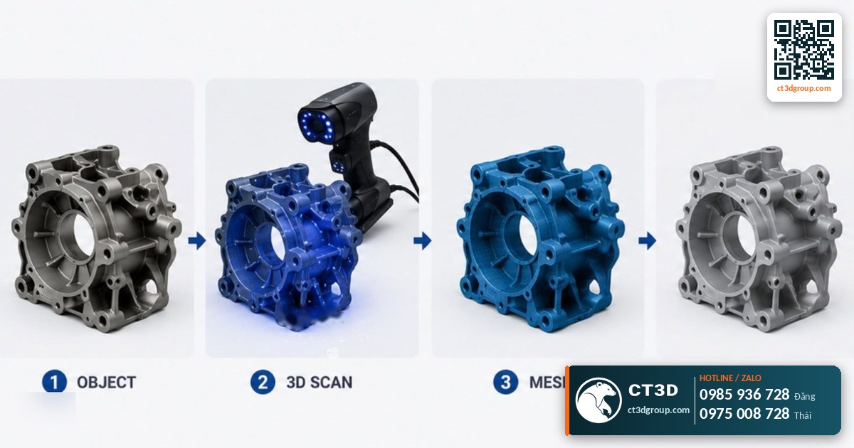
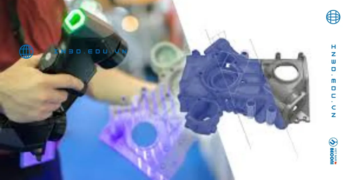
Technical summary: Reverse engineering at CT3D is the process of turning a physical object into an editable parametric CAD model. Inputs are 3D scan data (point cloud/mesh) combined with manual measurements using calipers and micrometers; outputs are STEP/IGES files or native files with a full feature tree, plus 2D drawings with tolerances when required. Our reverse engineering service in Vietnam helps you remanufacture parts with no drawings, improve existing products, or prepare data for CNC machining, mold making and 3D printing.
The typical customer has a worn, broken or discontinued part on the desk and no usable drawing. We scan it, measure the critical features by hand, rebuild the geometry to its design intent and check the result against the scan before handing over files your machinist, mold maker or 3D printing supplier can use straight away – including our own CNC machining and metal 3D printing. Send photos of the part for a fast quote; we sign an NDA on request.
Reverse Engineering Service at a Glance
| Inputs | Physical sample, photos or existing scan files; 3D scan plus caliper and micrometer measurements |
|---|---|
| Service levels | Clean mesh, freeform surfaces, parametric CAD, CAD with 2D drawings |
| CAD formats | STEP AP214/AP242, IGES, native files with feature tree |
| Drawings | PDF/DWG with tolerances and GD&T on request |
| Part materials | Engineering plastics, ferrous metals, aluminum, copper alloys, vulcanized rubber, wood, composites |
| Verification | CAD-to-scan deviation map, virtual assembly check, file integrity check |
| Where | In our workshop, or on site for large items and parts still installed on a machine |
When Do Companies Need a Reverse Engineering Service?
On the factory floor, the need typically arises in three situations. First, imported machinery has aged, the manufacturer has discontinued spare parts (obsolete parts) and no drawings were supplied. Second, a company wants to localize a part it currently imports, but the new supplier needs a CAD file to quote machining. Third, an R&D team needs the geometry of a reference product to design matching accessories or develop an improved version.
What all three have in common: the object exists, but the engineering data does not. Reverse engineering fills that gap through controlled measurement and modeling.
Scope of Work and Deliverables
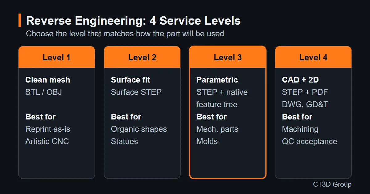
| Service level | Content | Output | Best for |
|---|---|---|---|
| Level 1 – Clean mesh | Scanning, alignment, hole filling, axis alignment | Watertight STL/OBJ | Reprinting as-is, artistic CNC |
| Level 2 – Freeform surfaces (surface fitting) | Automatic NURBS surfacing over the mesh | Surface STEP | Organic shapes, statues, parts with few mating dimensions |
| Level 3 – Parametric CAD | Rebuilt with sketches, extrudes, revolves and fillets following the design intent | STEP + native file with feature tree | Mechanical parts, molds, products that need modification |
| Level 4 – CAD + drawings | As Level 3, plus 2D drawings, tolerances, GD&T | STEP + PDF/DWG | Machining orders, quality acceptance |
Source: CT3D internal service levels; pricing is quoted per file and complexity.
Mesh vs. CAD Model: Why You Can’t Skip the Modeling Step
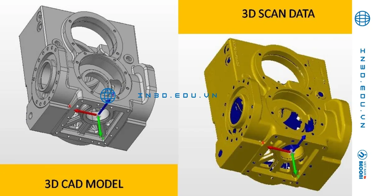
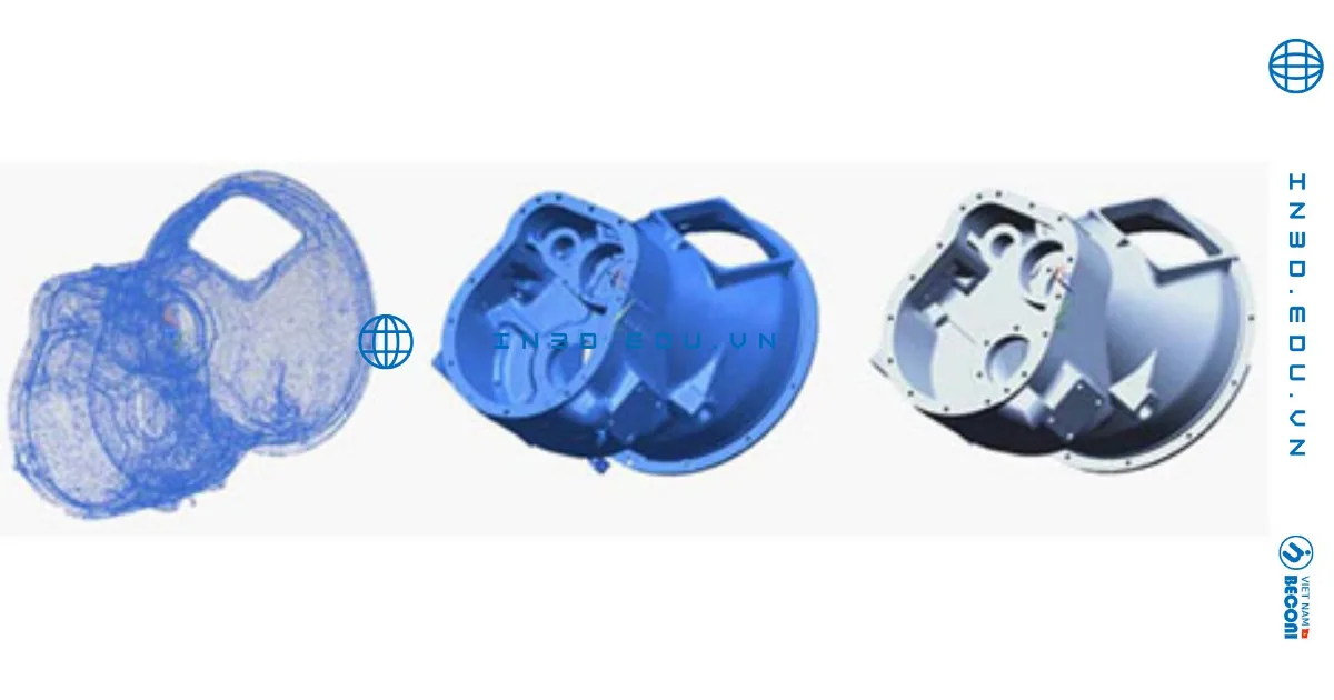
A scan file is a collection of hundreds of thousands to millions of small triangles. It captures the shape very faithfully – including wear, scratches and warpage from use. But it doesn’t “know” which faces are planes, which are cylinders or which holes are concentric. To change a hole diameter from 10 to 12 mm, extend a rib or produce a drawing for a machinist, you need a CAD model.
Modeling to design intent
CT3D engineers don’t copy every millimeter of wear. They identify the underlying geometric features – datum planes, rotation axes, bolt circles, draft angles – and round them to sensible nominal values. For example, if a worn part measures a 9.93 mm hole and it mates with a bolt, the engineer will set a nominal 10 mm hole with the appropriate fit tolerance.
Combining with contact measurement
Critical dimensions such as shaft diameters, hole center distances and keyway depths are re-measured with mechanical instruments and cross-checked against the scan data. This hybrid approach makes the model correct in overall shape and precise at the mating surfaces.
How Reverse Engineering Works: Our Workflow

- RFQ: send photos, the physical sample or existing scan files, and tell us the purpose (remanufacture, improvement, inspection) and the intended material.
- DFM review: our engineers determine the target manufacturing method (CNC, casting, injection molding, 3D printing), because it affects how the model is built: draft angles, tool radii, minimum wall thickness.
- Quotation: scanning and CAD modeling are itemized separately, with a delivery schedule.
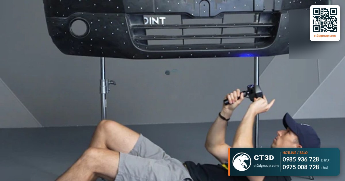
- Data acquisition: full 3D scan, manual measurement of mating surfaces, reference photos.
- Modeling: coordinate system alignment, region segmentation, sketches and features, with continuous deviation checks against the mesh.
- QC and delivery: CAD-to-scan deviation map, virtual assembly check with mating parts, delivery of files and drawings.
Part Materials and Data Standards
CT3D reverse engineers parts made of engineering plastics, ferrous metals, aluminum, copper alloys, vulcanized rubber, wood and composites. For heavily worn or broken metal parts, our engineers rebuild missing areas based on symmetry and mating parts. Data is delivered in neutral exchange formats – STEP AP214/AP242 or IGES – which open in virtually all mainstream CAD/CAM software. Drawings follow standard projection conventions and geometric tolerancing symbols familiar across the engineering industry.
| Target manufacturing method | What engineers watch for when building the CAD |
|---|---|
| 3/4/5-axis CNC machining | Internal corner radius ≥ tool radius; avoid deep, narrow pockets |
| Injection molding / die casting | Draft angles, uniform wall thickness, parting line |
| SLM metal 3D printing | Self-supporting angle around 45°, powder escape channels, machining allowance on mating faces |
| FDM/SLA plastic 3D printing | Minimum wall thickness, assembly clearances, print orientation and supports |
Source: common DFM/DfAM principles in manufacturing.
What to Send for a Reverse Engineering Quote
- Photos of the part from several sides, with a ruler or a known object in frame for scale.
- Purpose: remanufacture as-is, improve the design, inspect, or prepare a mold.
- Target manufacturing method and material (CNC, casting, injection molding, 3D printing) – it changes how the CAD is built.
- Mating parts or assembly context, if available, so fits can be checked virtually.
- Critical dimensions you already know, and any old drawings, even incomplete ones.
- Existing scan data in STL, OBJ, STEP or IGES, if you have it – we will tell you whether it is usable.
Industry Applications
- Industrial maintenance: gears, pulleys, agitator blades and clamps for imported production lines. See a typical case in our article on restoring discontinued spare parts.
- Automotive & motorcycles: plastic trims, brackets and aftermarket accessories that must fit existing frames.
- Tooling: rebuilding mold cavities from a sample product when the old mold is damaged or its data is lost.
- Consumer goods: competitor benchmarking, developing compatible accessories.
- Fine art & religious: rebuilding broken sections of statues, converting to CAD for scaling and machining.
Once the CAD is ready, the part can be produced by CNC machining (see our article comparing CNC and 3D printing) or by metal 3D printing when the geometry is complex.

Reverse Engineering vs. Other Ways to Recreate a Part
| Criteria | Scan-based reverse engineering | 3D scan (mesh) only | Redrawing from manual measurements |
|---|---|---|---|
| Freeform and curved surfaces | Captured and rebuilt as surfaces | Captured, but not editable | Hard to capture accurately |
| Editable dimensions | Yes – parametric feature tree | No | Yes |
| Wear and damage | Corrected to nominal design intent | Copied as-is | Depends on the person measuring |
| Verification | Color deviation map against the scan | Not applicable | Spot checks only |
| Best for | Complex parts, molds, parts that must fit an assembly | Reprinting or carving as-is | Simple prismatic parts with few features |
General comparison; for simple brackets or spacers, a drawing from measurements may be the cheapest route, and our engineers will say so.
Quality Control
Every delivered model is checked on three levels. Geometry: a color map comparing CAD to scan data, clearly marking areas that intentionally deviate because they were set to nominal dimensions. Fit: interference checks with mating parts when data is available. Data: the file opens in the customer’s software, solids are closed and there are no open faces. For production orders, we recommend a 3D printed first article (FAI) for a trial fit before machining the real material – significantly reducing the cost of corrections.
How to Order
- Send photos and requirements through the Contact form, email or Zalo.
- Get a free manufacturability review and quote, with scanning and CAD modeling itemized and a delivery schedule.
- Deliver the sample to one of our workshops or drop-off points, or book on-site scanning.
- Approve nominal dimensions where wear or damage required interpretation.
- Receive the CAD package – STEP, native files, drawings and deviation report as ordered – and, if needed, a test print or machined part.
Why CT3D for Reverse Engineering
- Scan plus hand measurement – full-surface data combined with caliper and micrometer checks on mating faces.
- Modeled to design intent, not a copy of the wear, with intentional deviations marked on the report.
- CAD built for your process – drafts, tool radii and wall thickness set for CNC, casting, molding or 3D printing.
- Production next door – CNC machining, metal and plastic 3D printing and mold making in the same company.
- Confidential and clear – NDA on request, itemized quotes, engineering support in English.
Frequently Asked Questions
How is reverse engineering different from 3D scanning?
3D scanning only captures the shape as a mesh. Reverse engineering uses that mesh as a base to build a CAD model with nominal dimensions that can be edited and used to produce drawings. Learn more about our 3D scanning service.
Can you work with worn or broken parts?
Yes. Our engineers use the remaining geometry, symmetry and mating parts to restore nominal dimensions, then confirm them with you before finalizing.
Which files will I receive?
At minimum a STEP file; depending on the package, also a native file with feature tree, STL for test printing, 2D drawings in PDF/DWG and a deviation report.
Do I need to send the sample to your workshop?
We recommend it so we can scan and measure directly. For large items or parts still installed on a machine, CT3D can scan on site.
Will the CAD model copy the wear on my part?
No. Engineers model to design intent: planes, axes, hole patterns and draft angles are identified and rounded to sensible nominal values, and mating dimensions are confirmed by hand measurement. Areas set to nominal values are marked on the deviation map so you can see where the CAD intentionally differs from the worn sample.
Can you improve the part while rebuilding it?
Yes. Because the result is a parametric model, features such as hole sizes, wall thickness or ribs can be changed during or after modeling. Tell us the changes and the target manufacturing method at the start so they are built into the model correctly.
Do you provide 2D drawings with tolerances?
Yes. Level 4 of our service adds 2D drawings with dimensional tolerances and GD&T in PDF or DWG, ready for machining orders and quality acceptance.
Can CT3D also manufacture the part?
Yes. Once the CAD is approved the part can be produced by CNC machining, metal or plastic 3D printing, or used to make molds. We usually recommend a 3D printed first article to check the fit before machining the final material.
Further reading: 3D scanning and reverse engineering in Ho Chi Minh City, Vietnam; accuracy and tolerances in 3D printing.
Watch: Real Footage from the CT3D Workshop
Watch the video 3D Scanning Service – CT3D Scan 3D to see our process and output quality first-hand. More videos are available on our channel Che Tao Vlog – CT3D (in Vietnamese).
Contact CT3D – Send Your Files for a Fast Quote
Whether you have a 3D file, 2D drawings, photos or just an idea, you can send it to CT3D. Our engineers will review your files (STL, STEP, IGES, OBJ), advise on technology and materials, and send a quotation with the delivery schedule.
- Email: [email protected] – [email protected]
- Phone / Zalo: +84 975 008 728 (Mr. Thai) – +84 985 936 728 (Mr. Dang), or use our Contact form
- Head office: Binh Duong, Vietnam.
- Workshops: Ho Chi Minh City, Vietnam (three locations).
- Other workshops and drop-off points: Can Tho, Da Nang, Bien Hoa, Ba Ria – Vung Tau, Hanoi, Hai Duong, Hai Phong. Nationwide delivery within Vietnam; international shipping on request.
- Website: ct3dgroup.com – in3d.edu.vn
CT3D – 3D design & prototyping: 3D printing, 3D scanning, reverse engineering, silicone mold making, painting & finishing, CNC machining, composite fabrication, plus 3D printers and 3D printing resins.
Need CAD for a Part With No Drawings?
Send photos of the part, its purpose and the target manufacturing method. Our engineers will review it and reply quickly with a quotation and schedule.