Industrial CT Scanning Vietnam – Porosity, Wall Thickness
Technical summary: Industrial computed tomography (industrial CT scanning) is a non-destructive testing (NDT) technique that reconstructs a full 3D volume of a part from hundreds to thousands of X-ray projections. The resulting voxel data enables porosity analysis, wall-thickness analysis, inspection of sealed assemblies, and comparison of both internal and external geometry against the CAD model. For our industrial CT inspection service in Vietnam, CT3D advises on the approach, coordinates the scan and processes the data into a technical report that can be used for acceptance.
CT is the right tool when the question is about what you cannot see: porosity inside a die-cast housing, trapped powder in a printed cooling channel, a misplaced spring inside a sealed product, or the real wall thickness of a hollow part. Because the part is not cut, the same sample can go on to functional testing, be returned to your supplier as evidence, or be kept as a reference.

Industrial CT Inspection at a Glance
| Method | X-ray computed tomography – non-destructive, full 3D volume (voxel data) |
|---|---|
| Analyses | Porosity and void statistics, cracks and inclusions, wall thickness maps, assembly checks, internal and external CAD comparison, surface extraction to STL |
| Best-suited materials | Plastics, resins and composites (excellent); aluminum and magnesium (good); steel, stainless steel and titanium (limited by thickness) |
| Our role | CT3D advises on the approach, coordinates the scan and processes the data into a technical report |
| Deliverables | PDF report with section images, color maps and data tables; mesh files or slice images on request |
| What to send | Photos, overall dimensions, material, number of samples, inspection goal, smallest defect to detect, CAD if comparison is needed |
| Pricing | Quoted per request by number of samples, resolution and level of analysis |
The Problems Industrial CT Solves
Traditional measurement methods such as calipers, coordinate measuring machines (CMM) or optical 3D scanning only reach visible surfaces. When a defect lies deep inside a casting wall, inside a weld, between 3D printed layers or within a sealed assembly, the only remaining option is often destructive testing. Sectioning consumes parts, reveals only a few cross-sections and may even alter the very defect you are looking for.
Industrial CT changes that approach. You receive a complete digital twin of the part that can be virtually sectioned along any plane, measured at any dimension, with every defect in the volume quantified – while the physical part remains intact for further testing or service.
How Volume Reconstruction Works
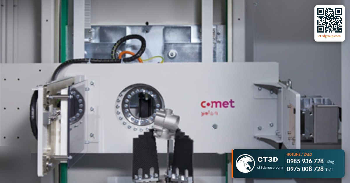
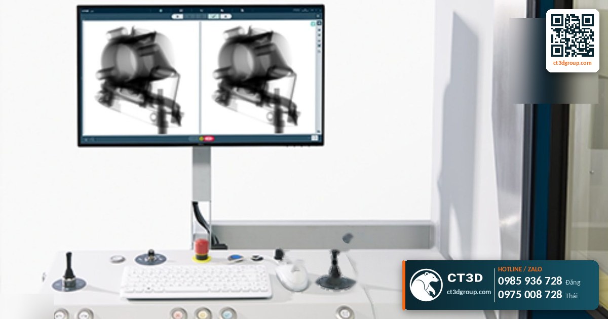
The part is placed on a rotary table between the X-ray source and the detector. At each rotation angle, the detector records a projection showing how much the beam is attenuated as it passes through the material. After a full rotation, a reconstruction algorithm combines the projections into a volumetric data set in which each volume element (voxel) carries a gray value corresponding to material density.
| Parameter | Technical meaning | Effect on results |
|---|---|---|
| Voxel size | Spatial resolution of the data | Smaller voxels reveal smaller defects, but the scan field shrinks relative to part size |
| Tube voltage (kV) | X-ray penetration capability | Dense, thick materials such as steel need higher energy than plastics or aluminum |
| Number of projections | Angular sampling density | More projections reduce noise but increase scan time |
| Artifacts | Streaks, beam hardening | Require proper part orientation and filtering, especially for multi-material assemblies |
General principles of industrial CT; specific parameters are selected for each part and scanning system.
Choosing the Right Resolution
Resolution is the single most important decision in a CT job. As a rule of thumb, a defect needs to span several voxels to be detected and measured reliably, so the smallest feature you care about sets the voxel size you need. The catch is that voxel size is tied to the field of view: the larger the part, the coarser the voxels in a single scan. Typical options when the part is large but the defect is small:
- Region-of-interest (ROI) scan: scan only the critical zone at higher magnification.
- Overview plus detail: one coarse scan of the whole part to find suspicious areas, then a fine scan of those areas.
- Cut-out sample: when destructive sampling is acceptable, a smaller section allows much finer voxels.
This is why CT3D engineers always ask for the smallest defect you need to detect before quoting – it decides whether one scan is enough or a combination is needed.
Scope of Analysis
- Porosity and gas void analysis: locate, measure volume and map the distribution of porosity in aluminum and zinc castings, injection-molded plastics and metal 3D printed parts.
- Crack and inclusion detection: planar defects, slag inclusions, delamination in composites or between printed layers.
- Wall-thickness measurement: thickness color maps for hollow parts, tubes, thin shells and conformal cooling channels in molds.
- Assembly inspection: verify the position of springs, pins, wires and solder joints inside sealed products.
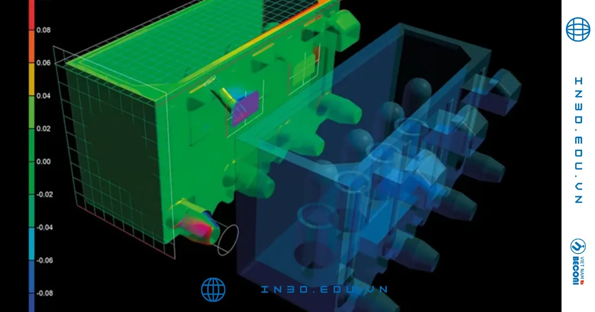
- CAD comparison: align CT data to the design model and output deviation color maps for both internal and external surfaces.
- Surface extraction for reverse engineering: convert volume data into STL meshes to rebuild CAD for parts with complex internal channels.
Typical Defects Found with Industrial CT
| Defect | Typical cause | What the CT report shows |
|---|---|---|
| Gas porosity | Trapped air or gas during casting or molding | Location, volume and size distribution of each void |
| Shrinkage porosity | Thick sections solidifying last | Clustered voids in hot spots, useful for gating changes |
| Cracks and delamination | Stress, poor layer bonding, impact damage | Extent and depth on virtual sections |
| Thin or uneven walls | Core shift, warpage, design errors | Wall thickness color map against the minimum allowed |
| Trapped powder or resin | Incomplete cleaning of internal channels in printed parts | Blocked or partly filled channels |
| Assembly errors | Missing, misplaced or deformed internal components | Position of springs, pins, wires and joints inside closed products |
General defect types; what can be detected in a given part depends on its size, material and the achievable resolution.
Suitable Materials and Known Limitations
| Material group | Suitability | Notes |
|---|---|---|
| Plastics, resins, composites | Excellent | High contrast with voids; small voxel sizes achievable |
| Aluminum, magnesium | Good | Common for die-casting inspection |
| Steel, stainless steel, titanium | Limited | Depends on penetration thickness; thick parts need high energy |
| Multi-material assemblies | Needs optimization | Heavy metals next to plastics cause artifacts; scan orientation must be chosen carefully |
For this reason, before accepting an order, CT3D engineers always ask for the overall dimensions, material and smallest defect to be detected in order to determine a feasible approach.
Workflow
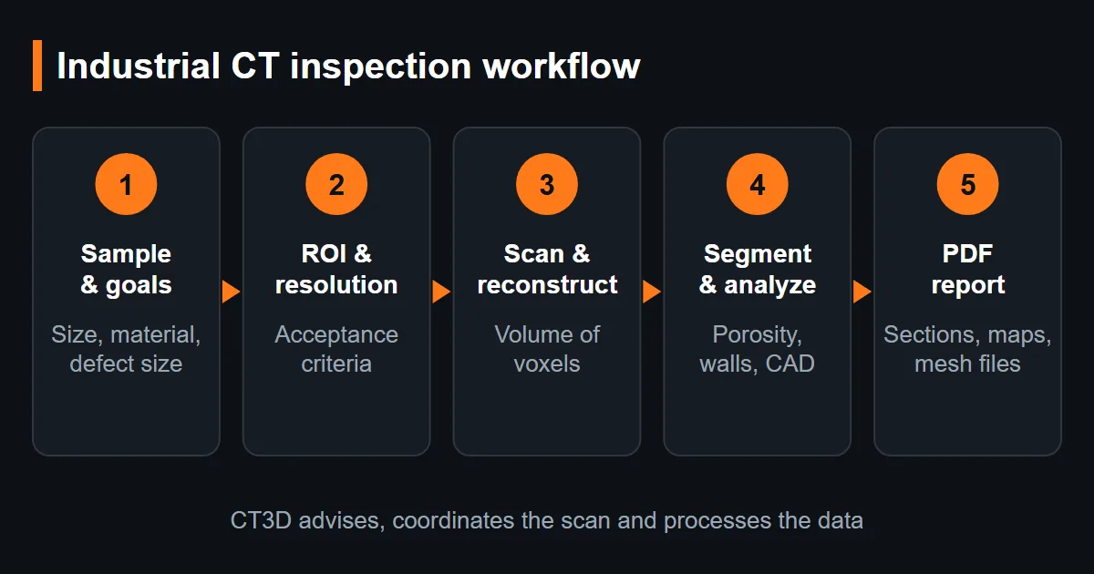
- RFQ: send us photos, dimensions, material, number of samples and inspection objectives, plus CAD files if a comparison is required.
- Technical review: define the region of interest (ROI), required resolution and defect acceptance criteria.
- Quotation and lead time: based on number of samples, resolution and level of analysis; quoted on request.
- Scanning and reconstruction: fixture the part, set parameters, scan and reconstruct the volume.
- Data analysis: segmentation, porosity statistics, dimensional measurement, CAD comparison.
- Delivery: PDF report with section images, color maps and data tables; mesh files or slice images if needed.
Industry Applications
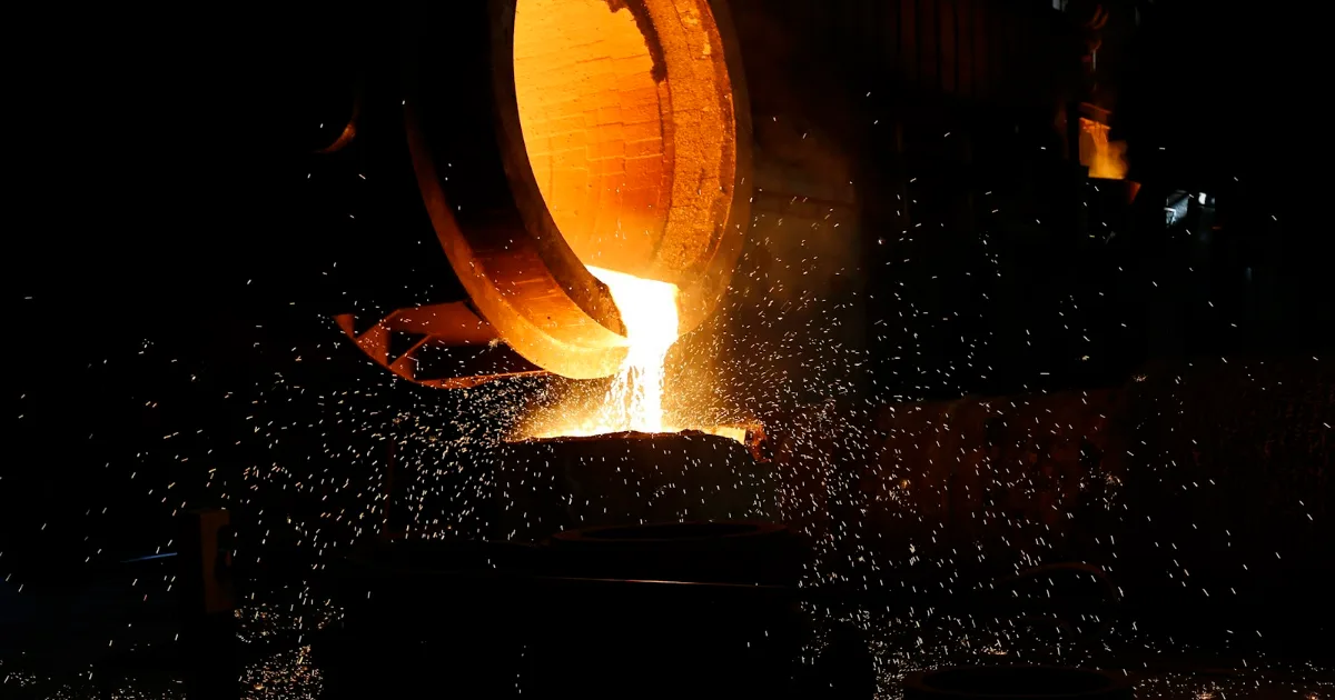
- Metal casting: evaluate shrinkage and gas porosity on first articles and optimize the gating system before series production.
- Injection molding: detect voids in thick sections, inspect metal inserts and internal warpage.
- Metal and plastic 3D printing: check density, trapped powder in internal channels and lattice deviations. See also our metal 3D printing (SLM) service and post-processing of metal printed parts.
- Electronics: solder joints, connectors, battery packs, packaged components.
- Failure analysis: find the root cause of fractures and leaks without destroying the evidence.
Industrial CT vs Other Inspection Methods
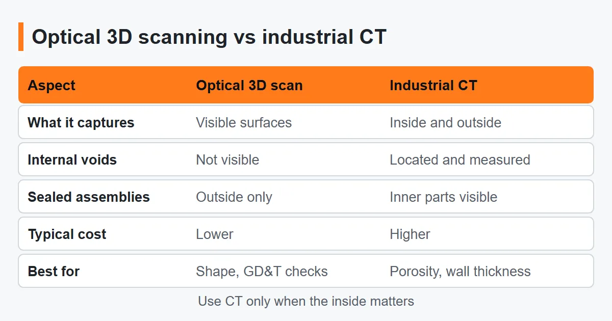
| Criterion | Destructive sectioning | 2D X-ray radiography | Optical 3D scanning | Industrial CT |
|---|---|---|---|---|
| Part kept intact | No | Yes | Yes | Yes |
| Internal features | Only on the cut plane | Yes, but overlapped in one projection | No | Yes, in full 3D |
| Defect location in depth | On the cut only | Hard to judge | Not applicable | Exact 3D position |
| Dimensional measurement | On the section | Limited | External surfaces | Internal and external |
| Typical cost per sample | Low, but the part is lost | Low to medium | Low to medium | Higher |
General comparison of methods; the best choice depends on what you need to find.
Data Quality Control
A CT report is only as valuable as the data behind it. CT3D controls three points: actual resolution matched to the size of the defects being sought; surface segmentation thresholds defined consistently across samples; and CAD alignment with the method clearly documented (datum-based or best-fit) so results are repeatable. When only the external surface needs inspection, CT3D will recommend optical 3D scanning to save cost.
How to Order CT Inspection
- Describe the job: send photos, dimensions, material, number of samples, the inspection goal and the smallest defect to detect through our contact form; add CAD (STEP, IGES) if a comparison is needed. An NDA is available on request.
- Feasibility and quote: our engineers confirm whether CT is the right method, agree the region of interest and resolution, and reply quickly with a quotation.
- Send the samples: we coordinate the scan and reconstruction.
- Receive the report: analysis, section images, color maps and data tables, with a walkthrough of the results if you need it.
Why Work with CT3D on CT Inspection
- Honest method advice: if optical scanning or a CMM answers your question, we will tell you before you pay for CT.
- Feasibility first: dimensions, material and smallest defect are checked before we accept the job.
- Repeatable analysis: consistent segmentation thresholds and a documented alignment method on every report.
- Connected services: CT surfaces can feed reverse engineering, and results can be compared with optical 3D scanning inspection data.
- Confidential handling and English-speaking engineers for international clients.
Frequently Asked Questions (FAQ)
How is industrial CT different from optical 3D scanning?
Optical scanning only captures visible surfaces. CT uses X-rays, so it also captures internal structures, voids and hidden surfaces.
Does CT scanning damage the part?
No. It is a non-destructive method; the part is returned in its original condition for further use or other testing.
How small a void can be detected?
It depends on the part’s size and material, because they determine the achievable voxel size. Our engineers will confirm after reviewing the sample.
How is CT inspection priced?
By number of samples, required resolution and level of analysis and reporting; CT3D quotes each request individually.
Can CT inspect steel parts?
Yes, within limits. Dense metals need higher X-ray energy and penetration thickness is restricted, so thick steel, stainless steel or titanium parts may not be suitable. Plastics, composites and aluminum give the best results.
Can CT measure dimensions as well as defects?
Yes. The volume can be compared with your CAD model for internal and external surfaces, and wall thickness can be mapped across the whole part.
What information do you need for a quote?
Photos, overall dimensions, material, number of samples, the inspection goal and the smallest defect you need to find, plus a CAD file if a comparison is required.
Can CT data be used for reverse engineering?
Yes. The volume can be converted into an STL mesh, which is useful for rebuilding CAD of parts with complex internal channels.
Real Footage from the CT3D Workshop
Watch the video 3D Scanning Service – CT3D Scan 3D, produced by CT3D, to get a clearer picture of our process and product quality. More videos are available on the Chế Tạo Vlog – CT3D YouTube channel.
Contact CT3D – Send Your Files for a Fast Quote
Whether you have a 3D file, 2D drawings, photos or just an idea, you can send it to CT3D. Our engineers will review your files, advise on technology and materials, and send a quotation with lead time. Files can be sent online (STL, STEP, IGES, OBJ).
- Email: [email protected] – [email protected]
- Phone / Zalo: +84 975 008 728 (Mr. Thai) – +84 985 936 728 (Mr. Dang) – or use our Contact form
- Headquarters: Binh Duong, Vietnam.
- Workshops: Ho Chi Minh City, Vietnam.
- Other workshops and drop-off points: Can Tho, Da Nang, Bien Hoa, Ba Ria – Vung Tau, Hanoi, Hai Duong, Hai Phong. Nationwide delivery across Vietnam, with international shipping available.
- Website: ct3dgroup.com – in3d.edu.vn
CT3D – 3D design & prototyping: 3D printing, 3D scanning, reverse engineering, silicone mold making, paint finishing, CNC machining, composite fabrication, and supply of 3D printers and 3D printing resins/filaments.
Need to See Inside Your Part?
Tell us the part, material and the defect you are looking for – we will confirm feasibility and send a quote.