
Industrial Design Service in Vietnam – ID + Rapid Prototyping
Technical summary: CT3D offers an industrial design service in Vietnam that develops product form using an Industrial Design (ID) approach, backed by in-house rapid prototyping in the same workshop. The output goes well beyond renders: every design concept is converted into CAD surface data (surface/solid, STEP), checked for manufacturability (DFM) for injection molding, CNC machining or 3D printing, and built as an appearance model or functional prototype so you can evaluate ergonomics and aesthetics before investing in tooling.
The service suits start-ups preparing a first product, manufacturers refreshing an existing line, and engineering teams that need an outside design partner able to hand over production-ready files rather than mood images. You can order the full process or only the phases you need – for example, engineering an existing concept for molding, or building presentation models from your own CAD.
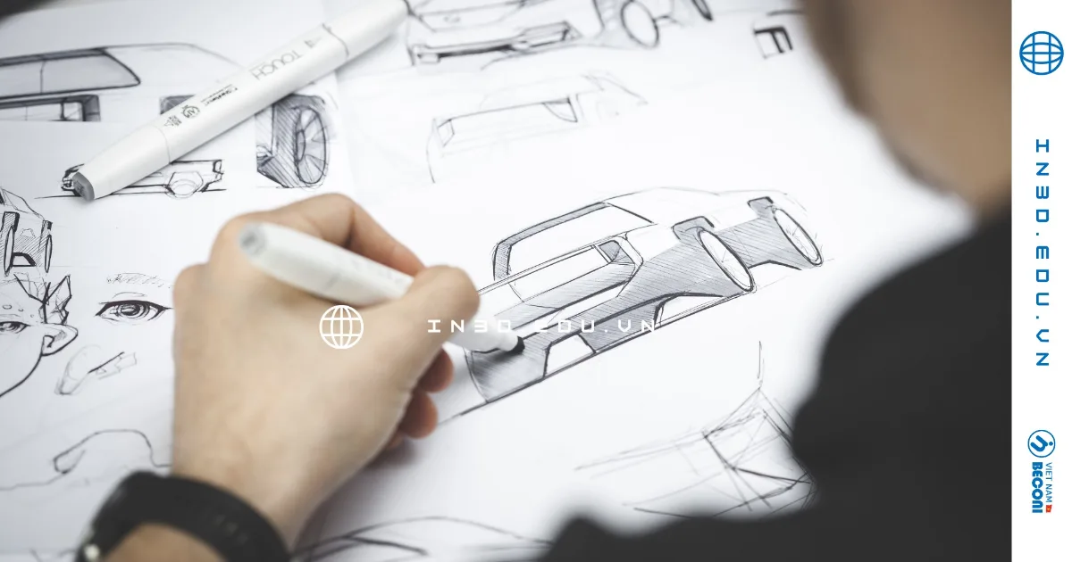
Industrial Design Service at a Glance
| What you get | Design brief, 2–3 concept directions, renders, CAD surface files, STEP solids and assemblies, key drawings, CMF sheet, physical model |
|---|---|
| Prototype technologies | FDM (PLA, PETG), SLA/DLP resin, MJF/SLS PA12, Tough/ABS-like resin, plating and metallic paint |
| Reference prototype tolerances | ±0.1–0.3 mm (FDM) · ±0.05–0.1 mm (SLA/DLP) · ±0.05–0.15 mm (functional models) |
| Target production methods | Injection molding, CNC machining, 3D printing, silicone molds with PU casting (vacuum casting) |
| Files we accept | STL, STEP, IGES, OBJ, 2D drawings, sketches, photos or a written brief |
| Quotation | Phased – approve and pay milestone by milestone; free manufacturability review with the quote |
| Confidentiality | NDA signed on request before you share drawings or product plans |
The Role of Industrial Design in Product Development
In the New Product Development (NPD) cycle, industrial design sits between user research and engineering design. Decisions made at this stage – form, proportions, part split lines, hand-contact surfaces – drive most of the tooling and assembly cost later on. Changing a curve while it is still a sketch costs almost nothing; changing it after a steel mold has been machined is far more expensive. That is why CT3D runs manufacturability checks in parallel with the creative work instead of leaving them to the end.
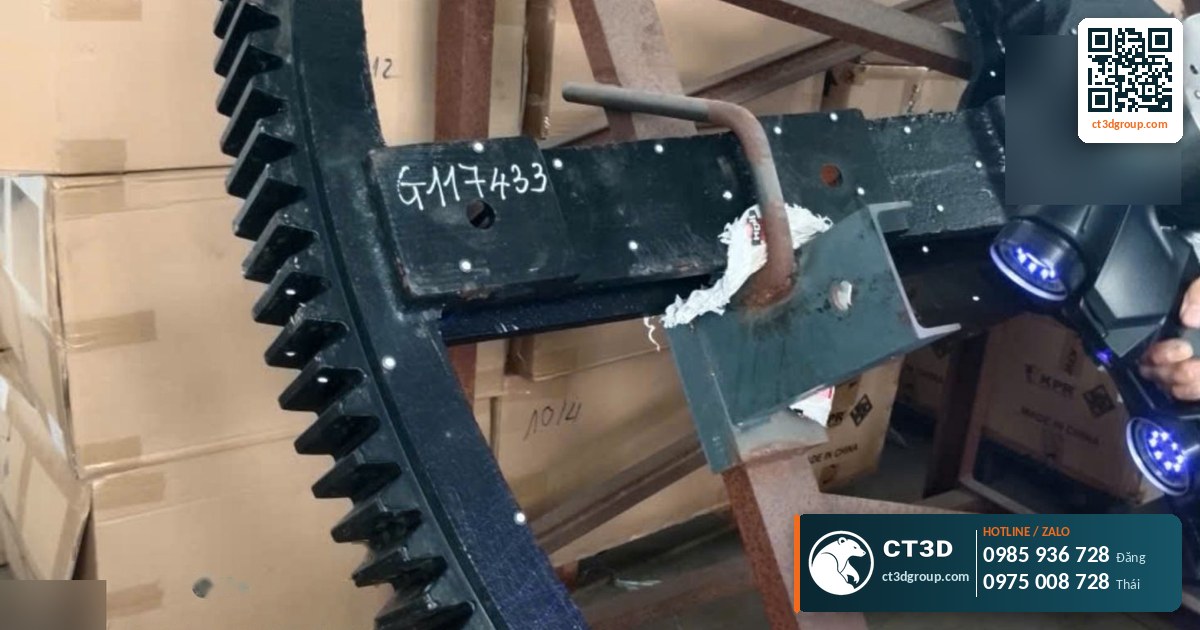
How the Industrial Design Process Works
Every project moves through five phases with a clear deliverable and an approval point at the end of each. Because the phases are quoted separately, you only commit budget to the next step once the previous one meets your expectations.
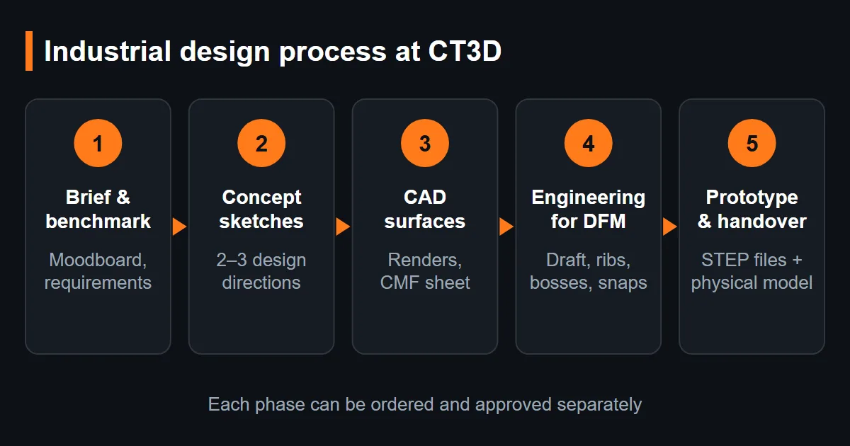
| Phase | Activities | Deliverables |
|---|---|---|
| 1. Direction | Competitive benchmarking, moodboard, technical requirements | Design brief |
| 2. Concept | 2D sketches, preliminary 3D form studies | 2–3 design directions to choose from |
| 3. Development | CAD surface modeling, color – material – finish (CMF) | Renders, CAD surface files |
| 4. Engineering | Housing split, ribs, screw bosses, snap fits, draft angles | STEP solids, assemblies |
| 5. Prototyping | 3D printing, paint finishing, metallic-look plating | Appearance model / functional prototype |
Source: CT3D service process. Each phase can be ordered separately.
Balancing Three Axes: Form, Function and Manufacturability
Form and brand identity
The product form must express the brand’s design language: signature lines, proportions and characteristic details repeated across product lines. A CMF (Color – Material – Finish) sheet defines the color, gloss level and surface texture of each part.
Function and ergonomics
Grip zones, buttons and display viewing angles are checked on real printed models, not just on screen. Quick FDM prints are used to test how the product feels in the hand before a smooth-surface resin model is made.
Manufacturability
For injection-molded housings, our engineers check for uniform wall thickness to avoid sink marks, sufficient draft angles for part ejection, and parting-line positions that do not spoil visible surfaces. For low-volume production, small-batch 3D printing or silicone molds with PU casting (vacuum casting) can be more economical than steel tooling; our article on 3D printing vs. injection molding analyzes the break-even point.
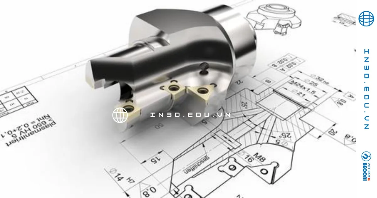
Design Guidelines for Manufacturable Product Housings
The values below are general industry guidance for plastic housings, not fixed CT3D rules. The right numbers always depend on the material, part size and the toolmaker’s process, which is why we confirm them during the engineering phase.
| Feature | General guidance | Why it matters |
|---|---|---|
| Wall thickness | Keep walls as uniform as possible; typically 1.5–3 mm for molded consumer housings | Uneven walls cool unevenly and cause sink marks and warpage |
| Draft angle | Typically at least 1° on vertical faces, more on textured surfaces | Lets the part release from the mold without sliders or drag marks |
| Ribs | Typically 50–60% of the adjoining wall thickness | Adds stiffness without creating visible sink on the outer surface |
| Screw bosses | Tie bosses to walls with ribs; avoid thick solid sections | Prevents voids and cracking around inserts and screws |
| Fillets | Round internal corners instead of leaving sharp edges | Reduces stress concentration and improves material flow |
| Parting line | Place it on an edge or feature line, away from hero surfaces | Keeps visible faces clean and simplifies the mold |
| Snap fits | Design for the material’s allowable strain and test on a printed prototype | Avoids clips that break or loosen after a few cycles |
Prototype Materials & Finishing Standards
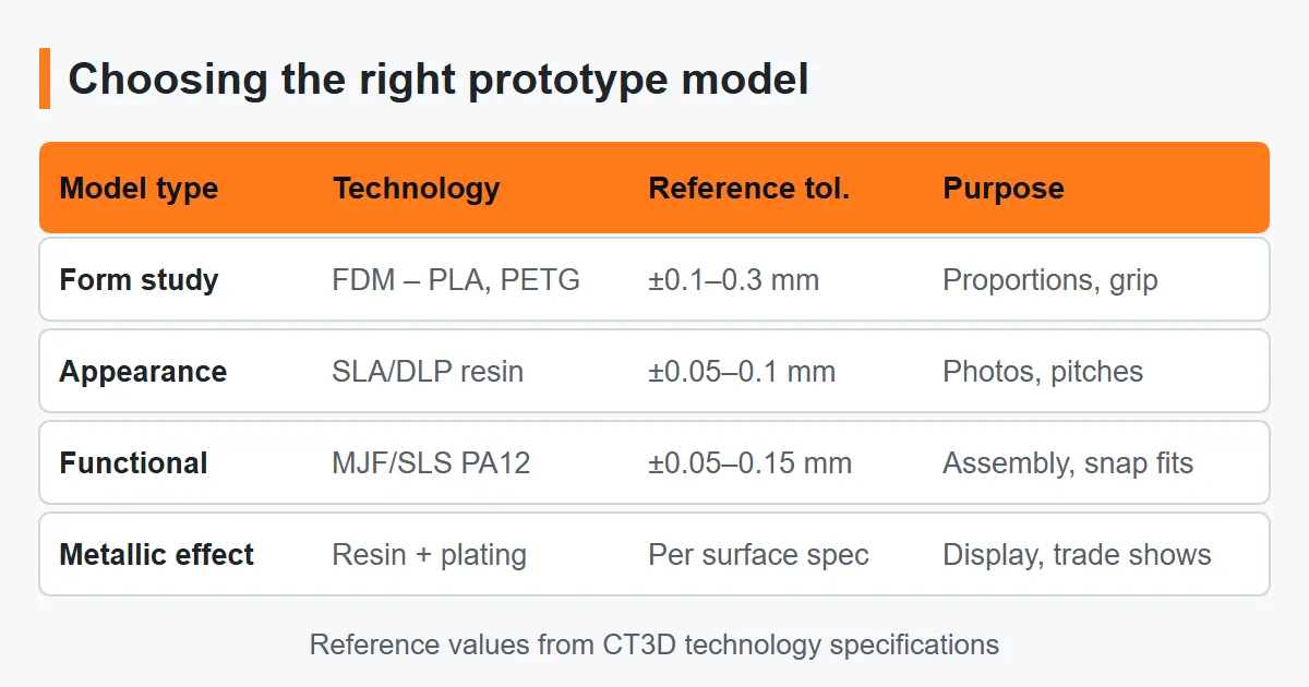
| Model type | Technology / material | Reference specs | Purpose |
|---|---|---|---|
| Form study model | FDM – PLA, PETG | 100–300 micron layers, ±0.1–0.3 mm | Evaluate proportions and grip |
| Appearance model | SLA/DLP resin, primer – color coat – clear gloss | 25–100 micron layers, ±0.05–0.1 mm | Photography, presentations, fundraising |
| Functional prototype | MJF/SLS PA12, Tough/ABS-like resin | ±0.05–0.15 mm | Assembly, snap-fit and durability testing |
| Metallic-effect model | Resin + plating / metallic paint | Per surface requirements | Display, trade shows |
Source: CT3D technology specifications 2026. For our painting process, see our 3D printing painting and plating service.
Finishing Options for Design Models
- Raw print: fastest option for internal form reviews and ergonomic checks.
- Sanded and primed: smooth, neutral surface that shows true form without color distraction.
- Color coat and clear gloss: painted to the CMF sheet for photography, investor presentations and user testing.
- Metallic paint or plating: chrome-, gold- or metal-look surfaces on resin models for display and trade shows.
- Mixed finishes: matte body with gloss accents, or different colors per part, to match the planned production look.
Workflow
- RFQ: send us a product description, target users, expected production volume, target unit cost and any internal components (with dimensions, if available).
- Upfront DFM review: we identify the intended mass-production method so the design constraints are set from day one.
- Phased quotation: you can approve and pay milestone by milestone.
- Concept creation and approval: sketches, renders, selection of one direction to develop.
- Engineering and prototyping: production-ready CAD, printed models, paint finishing; review and refine.
- QC and handover: STEP file set, key drawings, CMF sheet, physical model; support for discussions with your toolmaker.
Industry Applications
- Electronics and IoT devices: sensor housings, controllers, handheld devices requiring layout of PCBs, batteries and connectors.
- Household products: handles, lids, small appliance bodies, kitchen accessories.
- Premium packaging: cosmetic bottles and jars, signature caps, display boxes.
- Industrial equipment: machine housings, control panels, safety handles.
- Gifts and displays: trophies, commemorative medals, scaled-up product models.
Companies refreshing the look of an existing product can combine industrial design with 3D scanning and reverse engineering to keep the internal mechanics unchanged. If you only need a part modeled to existing requirements, our 3D CAD design service or concept-to-3D design may be a better fit.

Renders, Appearance Models or Functional Prototypes?
Each validation method answers a different question. Most projects use more than one, moving from cheap and fast to more realistic as the design firms up.
| Criterion | Renders only | Appearance model | Functional prototype |
|---|---|---|---|
| What it proves | Overall look, color options | Real proportions, color and surface quality | Fit, assembly, snap fits, basic durability |
| Typical speed | Fastest | Moderate (print plus painting) | Moderate |
| Typical cost | Lowest | Medium | Medium |
| Hand feel and ergonomics | Not possible | Yes | Yes |
| Best used for | Early concept selection | Photography, pitches, user testing | Engineering sign-off before tooling |
General comparison; actual time and cost depend on size, quantity and finish.
Common Mistakes in In-House Product Styling
From the projects that reach our workshop, CT3D sees a few recurring mistakes. First, designing the housing before fitting the components, which forces the housing to grow or the PCB to change. Second, surfaces that look great in renders but have uneven wall thickness, leading to sink marks and warpage during injection molding. Third, ignoring draft on vertical faces, which forces the toolmaker to add sliders and increases cost. Fourth, choosing colors on screen and going to production without a physical color sample. The fix: include the component list and the production method in the brief from the start, and always run at least one round of printed prototypes.
Quality Control
CT3D controls design quality through design gates with clear criteria. At the engineering gate, files undergo wall-thickness analysis, draft analysis, surface continuity checks (G1/G2) on visible areas, and interference checks between the housing and components. At the prototyping gate, printed models are measured at mating dimensions, snap fits are opened and closed, and colors are checked against the CMF sheet under the same lighting conditions. Every change is logged in a revision tracker so the final delivered file set is unique and consistent.
How to Order
- Send your brief: a description, sketches, photos or existing files (STL, STEP, IGES, OBJ) through our contact form or by email. Ask for an NDA first if needed.
- Review and phased quote: our engineers confirm the production method, scope and milestones, and we reply quickly with a quotation.
- Approve phase by phase: you review sketches, renders, CAD and models at each gate before the next phase starts.
- Handover: you receive the STEP file set, drawings, CMF sheet and physical model, delivered across Vietnam or shipped internationally on request.
Why Work with CT3D on Industrial Design
- Design and prototyping under one roof: the same team that draws the concept prints, paints and checks the model.
- Manufacturability from day one: DFM checks run alongside the creative work, not after it.
- Phased, transparent quotation: pay milestone by milestone and stop at any phase.
- Production-ready deliverables: STEP solids, assemblies and drawings your toolmaker can use directly.
- Confidentiality: NDA on request; your files are used only for your project.
- Engineering support in English for international clients, with international shipping on request.
Frequently Asked Questions
How is industrial design different from regular 3D design?
Regular 3D design models a part to existing requirements. Industrial design creates those requirements: form, user experience and CMF, while ensuring the product can be manufactured.
Can I register a design patent after the design is complete?
Yes. The files and models CT3D delivers can be used as supporting documentation for your application; the legal filing itself is handled by you or your intellectual property agent.
Do I need a physical model, or are renders enough?
We recommend a physical model. Proportions, hand feel and real colors often differ from renders; a printed model helps catch problems before tooling.
How is pricing calculated?
By phase and product complexity; CT3D provides a quotation after receiving your design brief.
Can I order only one phase, such as engineering or prototyping?
Yes. Each phase can be ordered separately. For example, we can engineer your existing concept for injection molding, or build appearance models from CAD files you already have.
What should my design brief include?
A product description, target users, expected production volume, target unit cost and a list of internal components with dimensions. Sketches, reference products and photos are also helpful.
Which files will I receive at the end of the project?
A STEP file set with solids and assemblies, key drawings, renders, the CMF sheet and the physical model, plus support when you discuss the design with your toolmaker.
Will you sign an NDA before I share my product idea?
Yes. CT3D signs a non-disclosure agreement on request before you send drawings or product plans.
See also: product presentation models (appearance prototypes).
Real Footage from the CT3D Workshop
Watch the video 3D Scanning Service – CT3D Scan 3D, produced by CT3D, to get a clearer picture of our process and product quality. More videos are available on the Chế Tạo Vlog – CT3D YouTube channel.
Contact CT3D – Send Your Files for a Fast Quote
Whether you have a 3D file, 2D drawings, photos or just an idea, you can send it to CT3D. Our engineers will review your files, advise on technology and materials, and send a quotation with lead time. Files can be sent online (STL, STEP, IGES, OBJ).
- Email: [email protected] – [email protected]
- Phone / Zalo: +84 975 008 728 (Mr. Thai) – +84 985 936 728 (Mr. Dang) – or use our Contact form
- Headquarters: Binh Duong, Vietnam.
- Workshops: Ho Chi Minh City, Vietnam.
- Other workshops and drop-off points: Can Tho, Da Nang, Bien Hoa, Ba Ria – Vung Tau, Hanoi, Hai Duong, Hai Phong. Nationwide delivery across Vietnam, with international shipping available.
- Website: ct3dgroup.com – in3d.edu.vn
CT3D – 3D design & prototyping: 3D printing, 3D scanning, reverse engineering, silicone mold making, paint finishing, CNC machining, composite fabrication, and supply of 3D printers and 3D printing resins/filaments.
Ready to Start Your Industrial Design Project?
Send your brief, sketches or CAD files and get a phased quote with a free manufacturability review.