

Quick answer: Discontinued machine parts with no surviving drawings can still be remanufactured with a three-step process: 3D scan the old part, reverse engineer it into a clean CAD file, then produce it by SLM metal 3D printing and CNC-machine the mating surfaces. CT3D prints metal parts from a single unit, with a tolerance of ±0.02 mm and tensile strength equal to or 10–15% higher than castings. This approach can cut spare part import costs by up to 40% compared with waiting for an overseas order. Pricing is quoted based on the file and the condition of the sample.
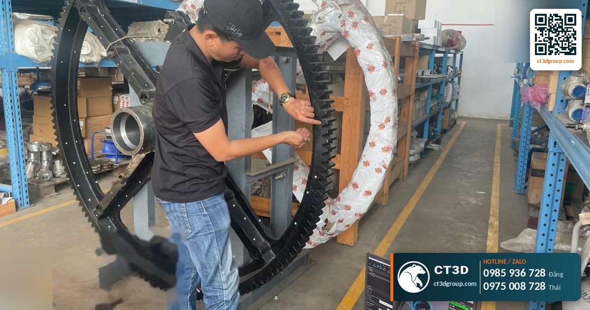
An imported production line has run well for years. Then an impeller, a lever or a pump housing wears out or breaks. The manufacturer has discontinued that model. The distributor has no stock, or the wait is very long. Nobody has the drawings. CT3D sees this situation regularly at factories. The solution is to combine 3D scanning, reverse engineering and metal 3D printing. This article walks through each step of spare part recovery with 3D scanning and metal printing, the technical points that are easy to get wrong, and how to prepare your sample for the best result.
Why Is Spare Part Recovery With 3D Scanning and Metal Printing So Effective?
The traditional method is to measure by hand with calipers, redraw in 2D, then cast or mill the part. That works for simple parts. For parts with freeform surfaces such as pump impellers, fan blades and manifolds, manual measurement is almost never accurate. Casting requires a pattern and a mold, which is not worth it for one or two parts.
3D scanning captures the entire surface of the part as a point cloud or triangle mesh. Reverse engineering turns that data into a clean CAD model with nominal dimensions and tolerances. Metal 3D printing produces the part directly from that file without tooling, starting from a single unit. Together, the three technologies form a closed loop.
| Criterion | Manual measurement + casting/milling | 3D scanning + reverse engineering + SLM printing |
|---|---|---|
| Freeform surfaces | Hard to measure, large deviations | Full surface captured |
| Casting mold needed | Yes, if cast | No |
| Economical quantity | Only worth tooling for larger quantities | From 1 part |
| Internal channels | Requires complex casting cores | Printed directly |
| Archiving for future reorders | 2D drawings, possibly incomplete | 3D CAD file, reprint any time |
| Design improvements | Difficult | Edited in CAD before printing |
Source: CT3D 3D scanning, reverse engineering and metal printing service workflow.
CT3D’s 6-Step Spare Part Recovery Process
Step 1 – Receive the sample and assess its condition
An engineer inspects the old part: where it is worn, where it is broken and how much remains intact. We also record which components it mates with, what loads it carries, its operating temperature and any chemical exposure. This information determines the print material and the tolerance level.
Step 2 – Clean and 3D scan
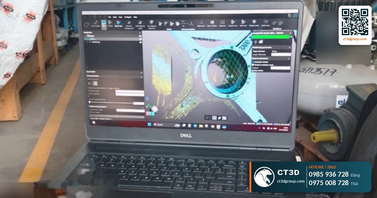
The part is cleaned of grease and rust. Surfaces that are too shiny or too dark may need a thin powder coating so the scanner can read them. The part is scanned from multiple angles and the scans are merged into a complete mesh. CT3D offers 3D scanning in Ho Chi Minh City and 3D scanning in Hanoi; customers in other provinces can ship their samples by courier.
Step 3 – Reverse engineer into clean CAD
This is the most important step and the most often misunderstood. A scan file is “a copy of the worn part”, not “the original design”. The engineer must rebuild a solid CAD model (STEP) with planes, cylinders and holes at their correct nominal dimensions. Freeform surfaces are rebuilt as NURBS surfaces that follow the scan data. See the next section for details.
Step 4 – Select material and prepare the print file
The engineer selects a material close to, or better than, the original. Machining allowance is added on mating surfaces, the build orientation is chosen and supports are designed.
Step 5 – SLM printing and post-processing
Parts are printed on German-standard machines at ±0.02 mm. After printing: stress-relief annealing, removal from the build plate, CNC machining of mating surfaces, bead blasting, and polishing or plating if needed. Each stage is covered in our article on metal 3D printing post-processing.
Step 6 – Inspection and test fit
The printed part is re-scanned and compared with the CAD model, producing a color deviation map. CT3D offers 3D inspection services (scan-to-CAD comparison, GD&T). You then test-fit the part in the machine. The CAD file is archived so the part can be reprinted next time without rescanning.
Reverse Engineering Worn Parts: Key Technical Points
Wear compensation – do not copy the worn surface
If you simply convert a scan into a print file, the new part will come out “pre-worn”, exactly like the old one. The engineer must identify the worn areas and rebuild the original geometry. Common methods:
- Compare worn areas with symmetrical, less-worn areas. For example, an impeller has several vanes; the least-worn vane becomes the reference.
- Use the mating part as a reference. For example, if a bore has worn oversize, reference the shaft diameter.
- Round to standard sizes. If a measured diameter is an odd value close to a standard size, the original dimension was most likely that standard size.
- Restore the planes, cylinders, concentricity and perpendicularity the original part certainly had.
Broken parts and missing fragments
If the broken pieces are available, each one is scanned and they are reassembled digitally. If pieces are missing, the engineer rebuilds them based on symmetry, mating parts or photos of the machine. You need to approve the rebuilt sections before printing.
Tolerances and fits
Scan data does not tell you the tolerances. The engineer needs to know whether the part has a clearance, transition or interference fit with other components. You should send the mating part or its actual measured dimensions. Mating surfaces are given machining allowance and CNC-machined after printing to achieve the correct fit.
Improving the design while remanufacturing
Once the CAD model is rebuilt, it can be improved – for example by thickening areas that tend to break, filleting sharp corners that concentrate stress, or switching to a stronger material. For internal channels, 3D printing allows smoother curves than the original casting could achieve. All changes should be documented and approved by the factory’s engineering team.
Choosing a Printable Replacement Material for the Original Part
Original parts are usually made of cast steel, cast iron, stainless steel, brass or cast aluminum. Not every material is available as an SLM powder. The table below gives guidance on replacement materials from CT3D’s catalog.
| Original part material | Suggested SLM replacement | Notes |
|---|---|---|
| Cast or wrought stainless steel | 316L, 304L, 17-4PH | 316L for corrosion resistance; 17-4PH is harder. See 316L stainless steel 3D printing |
| Cast aluminum | AlSi10Mg, AlSi12, AlSi7Mg | Composition close to common aluminum casting alloys. See AlSi10Mg aluminum 3D printing |
| Tool steel, wear parts | H13, Maraging 18Ni300, M2, D2, 420 | Heat treatment required after printing |
| Copper, conductive copper alloys | Cu, CuCrZr, CuNiSiCr | Electrodes, heat-dissipating parts |
| High-temperature, hot-gas parts | Inconel 625/718, Hastelloy X | Turbines, combustion chambers, hot valves |
| Cast iron | Usually a suitable steel or stainless steel | Cast iron is rarely available as print powder; re-check loads and wear |
| Brass, bronze | CuNiSiCr or stainless steel depending on function | Check friction and corrosion |
Source: CT3D SLM material catalog 2026. The final choice must be confirmed by an engineer based on operating conditions.
If the original material is unknown, you can have its composition analyzed at a materials lab, or describe the operating conditions so CT3D engineers can recommend a safe material.
Common Risks and How to Avoid Them
| Risk | Cause | Prevention |
|---|---|---|
| New part does not fit | Worn dimensions copied; no tolerances | Wear compensation, reference the mating part, CNC the mating surfaces |
| Scan misses hidden areas | Deep cavities, small holes the scanner cannot reach | Scan from multiple angles; supplement with hand measurement; refer to photos and machine documentation |
| Part breaks again in the same spot | Original design flaw or higher actual loads | Thicken, add fillets, change material, analyze the failure cause |
| Rapid corrosion | Replacement material unsuited to the environment | Select material based on actual chemicals and temperature |
| Warping after printing | Residual stress, long thin parts | Stress-relief annealing, suitable build orientation, machining allowance |
| Part too large for the build volume | Exceeds 250×250×300 mm | Split into modules, or print the complex section and machine the rest |
Source: CT3D 3D scanning and metal printing project experience.
How to Calculate the Benefit of Remanufacturing a Spare Part
CT3D does not give fixed prices, because every part arrives in a different condition. But you can compare the two options with a simple calculation:
- Wait for an import: part price + shipping and duties + (days waiting × cost per day of downtime).
- Remanufacture: scanning + reverse engineering + printing + post-processing + (days of work × cost per day of downtime).
The cost of downtime per day is usually the largest figure, and only the factory knows it precisely. In addition, scanning and reverse engineering are one-time costs. From the second order on, you only pay for printing and post-processing. Many factories proactively digitize frequently failing parts to build a “digital spare parts warehouse” and print on demand. According to CT3D’s data, metal printing can reduce spare part import costs by up to 40%.
If the part is needed in large quantities or has a simple shape, CNC machining may be cheaper. See our metal 3D printing vs. CNC comparison to evaluate for yourself.
Checklist for a Spare Part Recovery Request
- The old part (even if broken – keep all pieces), or clear photos if you cannot send the sample yet.
- The mating part (if it can be removed) or its measured dimensions.
- Machine name, model, the part’s location in the machine, photos of it installed.
- Operating conditions: load, speed, temperature, chemicals, water or oil environment.
- Original material if known; hardness requirements.
- Quantity required and whether it is urgent.
- Old drawings or catalogs if available (useful even if incomplete).
Typical Applications
- Impellers, pump vanes, pump housings: freeform surfaces, hard to measure by hand, worn by sand and chemicals.
- Levers, cams and mechanism parts in older packaging and textile machines.
- Nozzles, spouts and manifolds with internal channels.
- Heat-resistant parts in furnaces and combustion chambers, made in Inconel.
- Electrodes and welding tips in CuCrZr copper.
For discontinued plastic parts, CT3D can also remanufacture them with engineering-plastic 3D printing. You can see more of our metal printing capabilities at in3d.edu.vn. When you have a part that needs recovering, send photos and a description to CT3D’s metal 3D printing team for a feasibility assessment.
Frequently Asked Questions
Can a spare part be remade without drawings?
Yes. CT3D 3D scans the old part, reverse engineers it into a CAD file, then prints it in metal by SLM and CNC-machines the mating surfaces. All we need is the old part or all of its broken pieces.
Will a remade worn part have the wrong dimensions?
Our engineers do not copy the worn surface; they compensate for wear by referencing less-worn areas, the mating part and standard dimensions to rebuild the original geometry.
Are metal 3D-printed spare parts as strong as the originals?
SLM-printed parts have tensile strength equal to or 10–15% higher than castings. The material is selected for the actual operating conditions and can be stronger than the original.
Can you remake just one spare part?
Yes. CT3D accepts metal printing orders from a single part. The CAD file is archived so it can be reprinted next time without rescanning.
Can I send samples from a distant province?
Yes. CT3D has workshops and drop-off points in many provinces, accepts samples via Viettel Post, Giao Hang Tiet Kiem and Vietnam Post, and delivers nationwide.
Real Footage From the CT3D Workshop
Watch the video 3D Scanning Service – CT3D Scan 3D by CT3D to get a clearer picture of the process and product quality. More videos are available on our YouTube channel Che Tao Vlog – CT3D.
Contact CT3D – Send Your File, Get a Fast Quote
Whether you have a 3D file, a 2D drawing, photos or just an idea, you can send it to CT3D. Our engineers will check the file, recommend the right technology and material, and send you a quote with a lead time.
- Email: [email protected] – [email protected]
- Hotline / Zalo: +84 975 008 728 (Mr. Thai) – +84 985 936 728 (Mr. Dang), or use our contact form
- Headquarters: Binh Duong.
- Workshops in Ho Chi Minh City: Linh Trung (Thu Duc), Tam Binh (Thu Duc), former District 6.
- Other workshops and drop-off points: Can Tho, Da Nang, Bien Hoa, Ba Ria – Vung Tau, Hanoi, Hai Duong, Hai Phong. Nationwide delivery across Vietnam.
- Website: ct3dgroup.com – in3d.edu.vn
CT3D – 3D design & prototyping: 3D printing, 3D scanning, reverse engineering, silicone mold making, finishing and painting, CNC machining, composite fabrication, plus 3D printers and 3D printing materials.
Danh sách cửa hàng:
CT3D là đơn vị cung cấp trọn gói các dịch vụ thiết kế và sản xuất theo yêu cầu tại TP.HCM và khu vực lân cận (Bình Dương, Đồng Nai, Long An…). Với năng lực khép kín từ thiết kế 3D, in 3D (FDM, resin/SLA, SLS, in 3D kim loại), scan 3D – thiết kế ngược, làm khuôn, đúc composite – poly resin – poly stone đến gia công CNC và sơn màu hoàn thiện, CT3D đồng hành cùng khách hàng qua toàn bộ quy trình – từ ý tưởng, bản vẽ hay sản phẩm mẫu đến thành phẩm hoàn chỉnh. Dù bạn cần tạo mẫu nhanh, sản xuất số lượng, chế tác tượng – mô hình – quà tặng hay linh kiện kỹ thuật, đội ngũ CT3D sẽ tư vấn công nghệ và vật liệu phù hợp, đảm bảo sản phẩm sắc nét, đúng yêu cầu và tối ưu chi phí. Khách hàng tại TP.HCM và vùng lân cận có thể trao đổi trực tiếp, gửi file online và nhận sản phẩm thuận tiện, hỗ trợ cả đơn gấp lẫn dự án số lượng.
CT3D cung cấp trọn gói các dịch vụ thiết kế và sản xuất theo yêu cầu, phục vụ khách hàng tại Hà Nội và các tỉnh lân cận (Bắc Ninh, Hưng Yên, Hải Phòng, Vĩnh Phúc…). Với năng lực khép kín từ thiết kế 3D, in 3D (FDM, resin/SLA, SLS, in 3D kim loại), scan 3D – thiết kế ngược, làm khuôn, đúc composite – poly resin – poly stone đến gia công CNC và sơn màu hoàn thiện, CT3D đồng hành cùng khách hàng qua toàn bộ quy trình – từ ý tưởng, bản vẽ hay sản phẩm mẫu đến thành phẩm hoàn chỉnh. Quy trình làm việc thuận tiện: bạn gửi file 3D hoặc mô tả ý tưởng qua online, đội ngũ CT3D tư vấn công nghệ – vật liệu, báo giá nhanh và giao hàng tận nơi tại Hà Nội. Dù bạn cần tạo mẫu nhanh, sản xuất số lượng, chế tác tượng – mô hình – quà tặng hay linh kiện kỹ thuật, CT3D đều đáp ứng với sản phẩm sắc nét, đúng yêu cầu và tối ưu chi phí.

