3D Scanning Service in Vietnam – Point Cloud, STL & STEP
Technical summary: CT3D provides an industrial 3D scanning service in Vietnam for accurate 3D digitization using non-contact optical scanning: structured light, laser triangulation and – for large objects – photogrammetry. The raw output is a point cloud, which we process into a triangle mesh (STL/OBJ/PLY) or convert into parametric CAD (STEP/IGES) when reverse engineering is required. Deliverables support 3D printing, CNC machining, deviation analysis and digital archiving. Quotes are based on object size, surface complexity and the required output format.
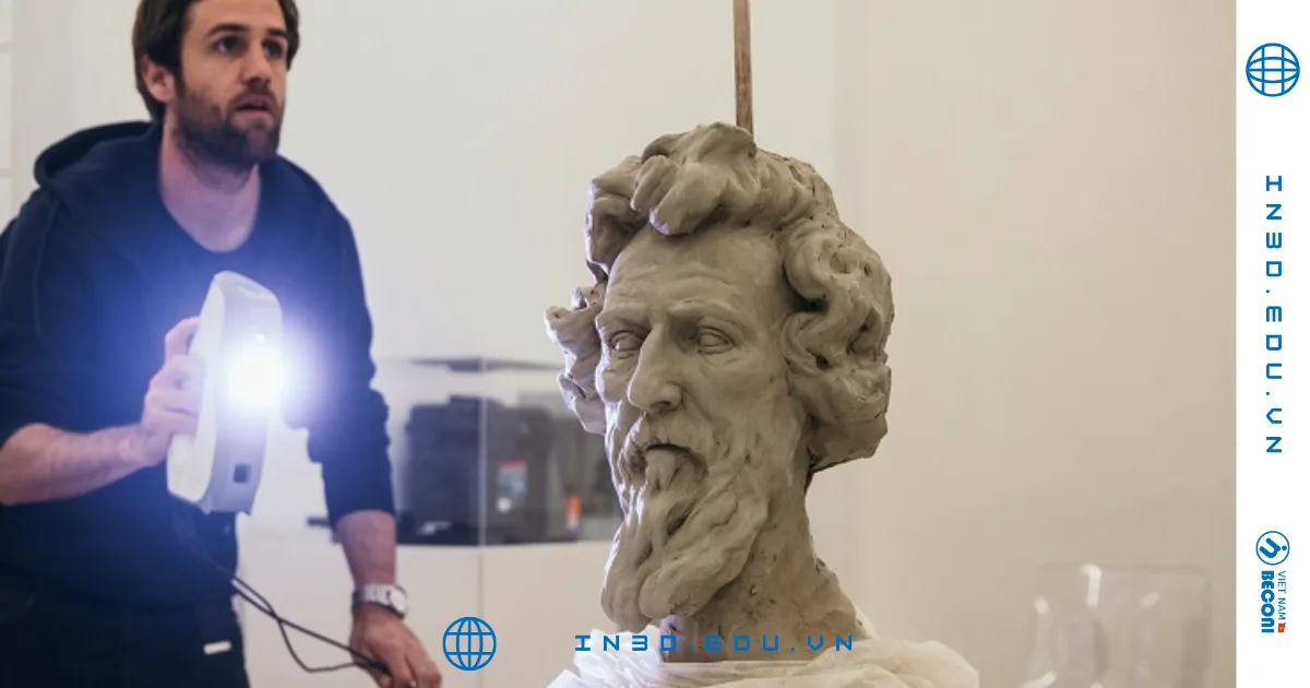
Whether you need a spare part with no drawings digitized, a sculpture captured for scaling, or a newly produced part checked against its nominal CAD, our 3D scanning service turns the physical object into data your team can use. Scanning can be done in our Ho Chi Minh City workshops or on site, and the same team can carry the data forward into reverse engineering, 3D printing or CNC machining. Send photos and rough dimensions of your part for a fast quote; we sign an NDA on request.
3D Scanning Service at a Glance
| Scanning technologies | Structured light, laser triangulation, photogrammetry for very large objects |
|---|---|
| Raw data | Registered point cloud (ASC, PLY, E57) |
| Mesh output | Watertight STL, OBJ (with texture if needed), PLY, 3MF |
| CAD output | STEP, IGES or native CAD files via scan-to-CAD |
| Inspection output | Deviation color map, cross-sections, PDF report |
| Object types | Mechanical parts, consumer products, statues and reliefs, figures and mascots |
| Where we scan | In our workshop or on site for objects that cannot be moved |
| Pricing | Quoted per project from photos or the physical sample – no fixed unit price |
Achievable accuracy depends on the scanner selected and on the object’s size and surface; our engineers confirm it in the quotation.
Scope of Our 3D Scanning Service
A scanning project is more than pressing a button and exporting a file. At CT3D every request is broken down into three layers of work: data acquisition, data processing and deliverables. You can order data acquisition only if your team handles processing in-house, or a turnkey package all the way to production-ready CAD files.
- Mechanical parts: housings, gears, pump impellers, brackets and obsolete parts that need to be remanufactured.
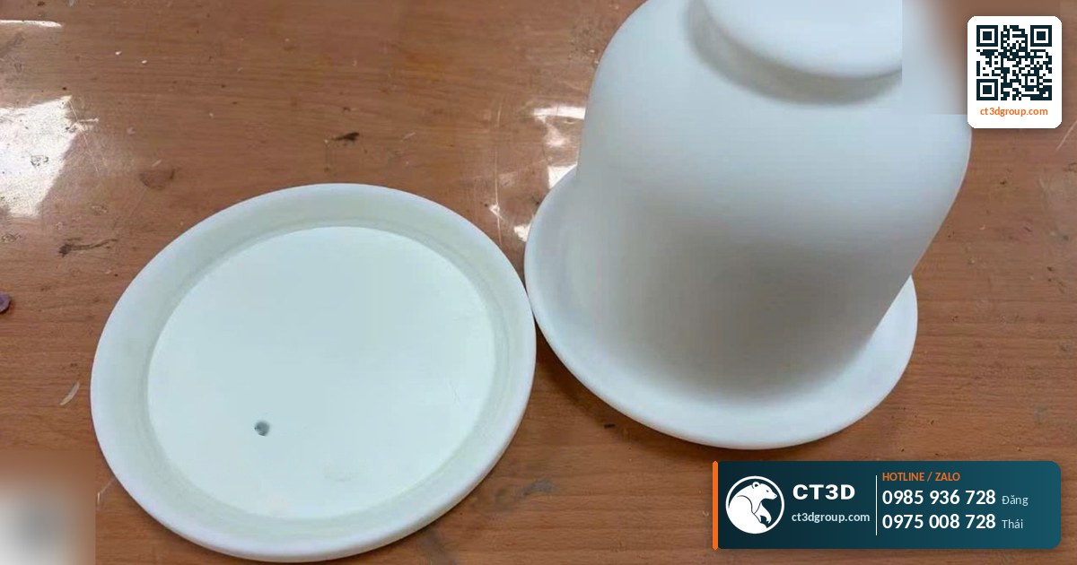
- Consumer products: bottles, caps, handles and household items for benchmarking or design refresh.
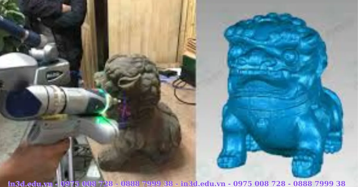
- Art and heritage: statues, reliefs, ornaments and religious artifacts for restoration and scaling up or down.
- Body and character scanning: for figures, mascots and personalized products.
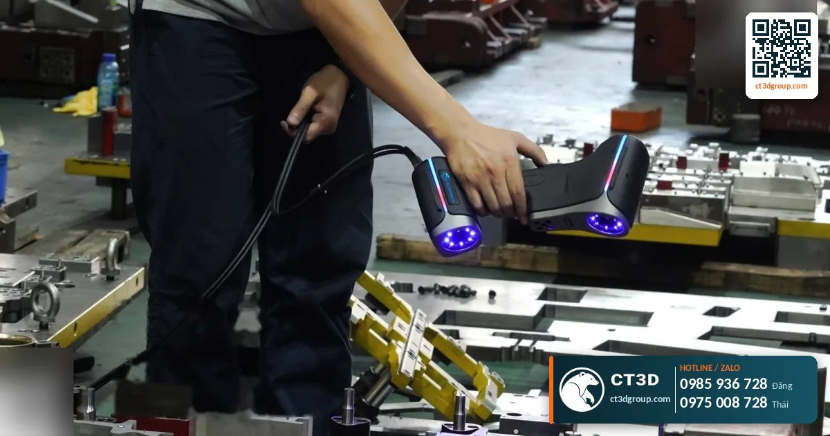
- On-site scanning: when the object is too large or cannot be removed from the factory or site.
| Technical item | CT3D approach | Notes |
|---|---|---|
| Measuring principle | Structured light, laser triangulation, photogrammetry | Selected by object size and surface material |
| Raw data | Registered point cloud | Multiple scans aligned using targets or geometry |
| Mesh output | STL, OBJ (with texture if needed), PLY | For 3D printing, visualization, archiving |
| CAD output | STEP, IGES, native CAD files | Via scan-to-CAD / reverse engineering |
| Inspection report | Deviation color map, cross-sections | Scan compared with nominal CAD, GD&T available |
| Lead time & price | Quoted per file / per physical sample | Depends on number of scans and processing workload |
Source: CT3D internal procedures. Actual accuracy depends on the selected equipment and on the object’s size and surface; our engineers confirm the specifics when quoting.
How 3D Scanning Works: From RFQ to Data Delivery
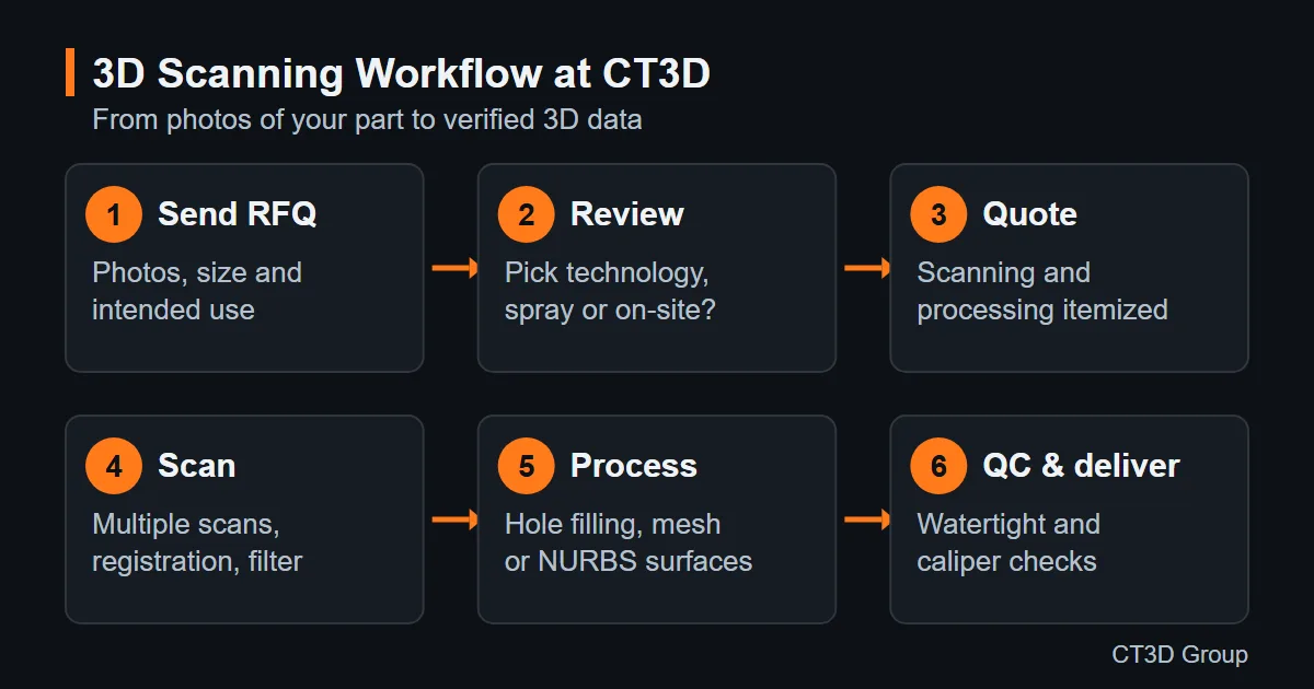
- RFQ: send photos of the part, its bounding-box dimensions and the intended use of the file (reprint, machining, inspection, archiving) via our Contact form, Zalo or email.
- Feasibility review: our engineers select the scanning technology, identify difficult areas and decide whether matting spray or on-site scanning is needed.
- Quotation and schedule: data acquisition and processing are itemized separately; you choose the output level (mesh or CAD).
- Data acquisition: multiple scans, alignment/registration and noise filtering.
- Processing and output: hole filling, controlled smoothing, decimation or NURBS surface reconstruction.
- QC and delivery: watertight check, dimensional verification against caliper measurements, file and report export; files are delivered by email or cloud drive, and samples are shipped back or collected at our workshop.
Measuring Principles and Choosing the Right 3D Scanning Technology
Structured light
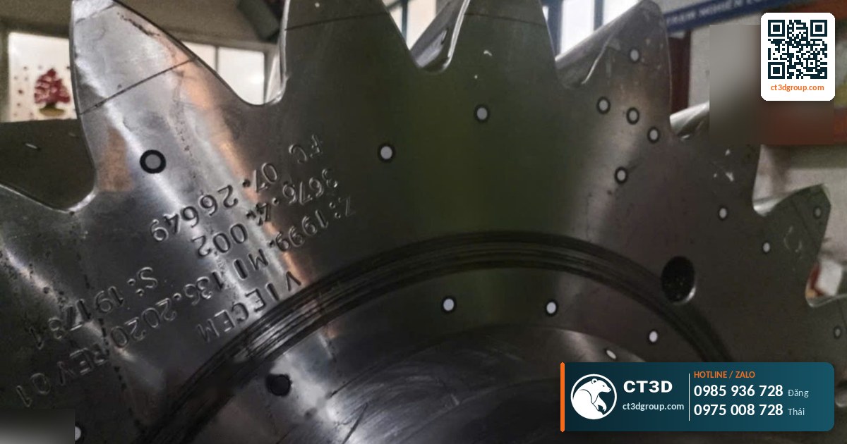
A projector casts a sequence of fringe patterns onto the surface; cameras capture how the patterns deform and calculate the coordinates of each point. This method delivers dense point data and suits small to medium parts with ribs, fillets and embossed text. Its weakness is sensitivity to ambient light and reflective surfaces.
Laser triangulation
A laser line sweeps across the object while a sensor measures the reflection angle to determine distance. Laser scanning copes better with dark surfaces and shop-floor conditions, making it the right choice for on-site scanning in factories or for black and machined metal parts.
Photogrammetry
Hundreds of photos are taken from different angles and the geometry is reconstructed algorithmically. We use this technique as a global reference frame for very large objects such as outdoor statues, then merge it with detailed scan data to retain both overall accuracy and local detail.
Quick comparison
| Criteria | Structured light | Laser triangulation | Photogrammetry |
|---|---|---|---|
| Typical object size | Small to medium parts | Medium parts, parts on site | Very large objects, outdoor statues |
| Detail capture | Very dense point data, fine features | Good, stable on edges | Overall shape; combined with scanning for detail |
| Dark or machined metal surfaces | Usually needs matting spray | Copes better | Needs texture or targets |
| Ambient light sensitivity | Higher – best indoors | Lower – suits shop floors | Needs even lighting |
| Main role at CT3D | Workshop scanning of parts and figures | On-site and difficult-surface scanning | Global reference frame for large objects |
General characteristics of each principle; the final choice is made per project during the feasibility review.
Difficult surfaces and how we handle them
Transparent, mirror-like, glossy black or very dark surfaces introduce noise into the optical signal. CT3D handles them with a self-evaporating matting scanning spray, reference targets and multiple part orientations. Deep cavities and narrow slots that light cannot reach are flagged as occluded areas and rebuilt during the CAD stage.
Materials, File Formats and Data Standards
Almost any solid material can be scanned: plastics, metals, wood, stone, ceramics, composites, plaster and stabilized fabric. What matters is that the object stays still and does not deform during measurement. For soft items such as low Shore A silicone, CT3D uses fixtures to prevent distortion.
| Format | Data type | When to use |
|---|---|---|
| Point cloud (ASC, PLY, E57) | XYZ point set, no surface yet | Archiving, surveying, processing in specialist software |
| Mesh STL / OBJ / 3MF | Watertight triangle mesh | 3D printing, artistic CNC, visualization, rendering |
| CAD NURBS (STEP / IGES) | Mathematical surfaces with editable dimensions | Machining, mold making, design modification |
| PDF report | Deviation color map, cross-sections, dimensions | QC, FAI (First Article Inspection), acceptance |
Source: industry-standard formats; CT3D exports to suit each project’s requirements.
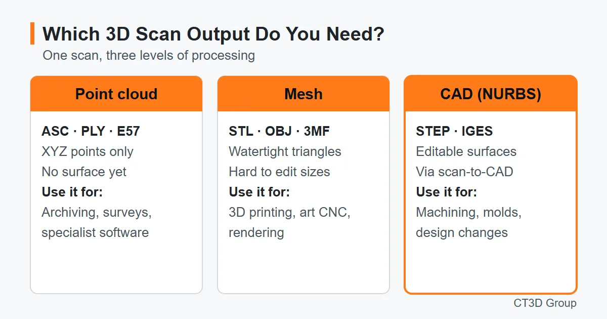
If you are unsure about the difference between a mesh and CAD, our article what is an STL file explains in detail why STL files print well but are hard to edit dimensionally. As a rule of thumb: if the file will only be reprinted or carved as it is, a mesh is enough; if anyone needs to change a dimension, machine a mating face or make a drawing, order CAD.
How to Prepare Your Part for 3D Scanning
A little preparation shortens the job and improves the result. These are general recommendations; our engineers will tell you what applies to your object.
- Clean the part. Oil, dust and loose debris show up as noise or false geometry. Remove what can safely be removed.
- Tell us which surfaces matter. Mark mating faces, holes, threads or datums that must be precise so they get extra scan coverage and caliper checks.
- Provide a few real dimensions. One or two measured values (overall length, a hole diameter) help confirm scale and catch errors early.
- Mention the surface finish. Clear, mirror-polished or glossy black parts usually need matting spray; let us know if spray is not acceptable on a valuable item.
- Separate assemblies if possible. Parts scanned individually are easier to align and model than a fixed assembly with hidden faces.
- State the end use. Reprinting, CNC machining, mold repair or inspection each lead to a different output and processing level.
Industry Applications
| Industry | Typical challenge | Recommended output |
|---|---|---|
| Engineering, plant maintenance | Remanufacturing parts with no drawings | Scan + CAD STEP for CNC machining or metal 3D printing |
| Tooling, casting | Checking worn molds, repairing mold cavities | Mesh + deviation map |
| Consumer goods | Product benchmarking, design refresh | Mesh as the base for Class-A surface reconstruction |
| Art, religious, heritage | Restoration, scaling, replication | High-resolution mesh for 3D printing or CNC |
| Education, research | Digitizing specimens, anatomical models | Textured OBJ, digital archive |
Published CT3D case studies include the restoration of the Our Lady of La Vang statue and several large Buddha statues, where scan data served as the basis for rebuilding damaged areas. The process is described in our article on statue restoration with 3D scanning. For industrial spare parts, see also our article on restoring spare parts with 3D scanning and metal 3D printing, and our reverse engineering service.
3D Scanning Compared with Other Measuring Methods
Optical scanning is not the only way to capture geometry. The table below shows, in general terms, where each method fits so you can judge whether scanning is the right tool for your part.
| Criteria | Optical 3D scanning | Manual measurement (calipers, gauges) | Contact CMM probing |
|---|---|---|---|
| What it captures | The complete surface as millions of points | Selected dimensions only | Selected points and features with high precision |
| Freeform and organic shapes | Very well suited | Poorly suited | Slow for freeform surfaces |
| Speed for a full part | Fast; most time goes into processing | Fast for a few dimensions, slow for full geometry | Slower; programming needed |
| Typical output | Point cloud, mesh, color deviation map | Hand sketch or table of values | Measurement report per feature |
| Best used for | Digitizing, reverse engineering, shape comparison | Checking a few critical sizes | Tight-tolerance acceptance of prismatic parts |
In practice the methods complement each other. CT3D combines full-surface scanning with caliper and micrometer checks on mating faces, so the data is correct both in overall shape and at the dimensions that matter for fit.
Quality Control of 3D Scan Data
A scan that looks good on screen is not necessarily usable. CT3D checks four criteria before delivery:
- Watertight mesh: no holes, no self-intersections and no non-manifold edges.
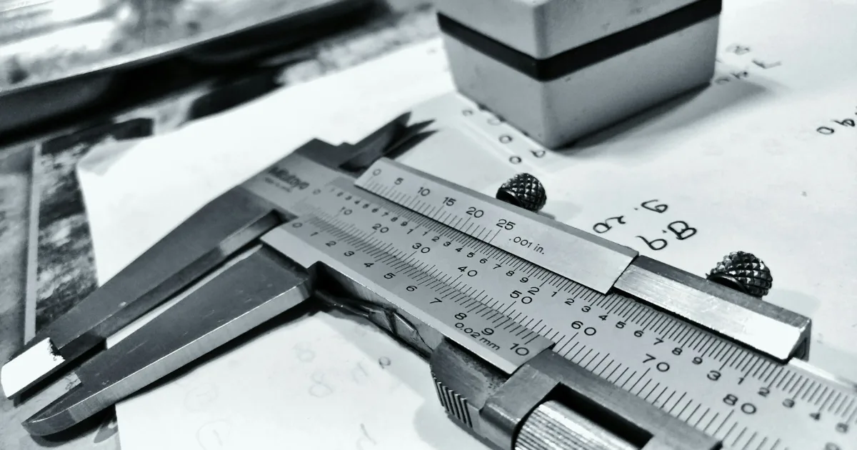
- Dimensional fidelity: reference dimensions are re-measured on the physical sample and compared with the file; if the deviation exceeds the agreed threshold, that area is rescanned.
- Mesh density fit for purpose: files for 3D printing must be fine enough not to show facets; files for CNC or CAD import must be light enough for the software to handle.
- Coordinate system: the scan is aligned to the part’s datums so that reverse engineers and machinists can work with it directly without re-aligning.
When you need acceptance inspection of newly produced parts, CT3D overlays the scan data on the nominal CAD using best-fit or datum-based alignment and exports a deviation color map, instantly revealing shrinkage, warpage or wear. Learn more about our 3D scanning inspection service.
Common DIY Scanning Mistakes and How CT3D Fixes Them
Many customers first try a low-cost handheld scanner or a phone app and then send us the file for printing. Typical problems: the mesh “melts” at sharp edges, flat faces become wavy, features under a few millimeters disappear, and threaded holes turn into bumps. The causes are usually insufficient scanner resolution, poor scan alignment or excessive smoothing. Our engineers will assess whether such files can be salvaged; if not, rescanning the physical sample is usually cheaper and faster than repairing the mesh by hand.
How to Order 3D Scanning from CT3D
- Send your request. Photos, overall dimensions, quantity and intended use – via the Contact form, email or Zalo. Existing STL, STEP, IGES or OBJ data is welcome too.
- Get a feasibility review and quote. We recommend the scanning method and output level, and itemize acquisition and processing so you only pay for what you need.
- Bring or ship the sample – or book on-site scanning. Parts can be dropped off at our workshops or collection points, or we come to your site.
- Receive checked data. Files arrive by email or cloud drive with any agreed report, and your sample is returned.
Why Choose CT3D for 3D Scanning
- Three measuring principles under one roof – structured light, laser triangulation and photogrammetry, chosen per object rather than forcing every job onto one scanner.
- Scan data that goes somewhere. The same team handles reverse engineering, 3D printing, CNC machining, mold making and finishing, so the file is prepared for the next step.
- Verified, not just exported. Watertight checks, caliper verification of reference dimensions and datum alignment before delivery.
- Workshop or on site. Workshops in Ho Chi Minh City plus drop-off points across Vietnam; on-site scanning for large or installed objects.
- Clear quotes and confidentiality. Acquisition and processing priced separately; NDA on request; engineering support in English.
Frequently Asked Questions
Can 3D scanning damage my sample?
No. Optical scanners never touch the object. Matting spray, if used, is self-evaporating or can be wiped off; CT3D will always ask first for high-value items.
Can I get a STEP file straight after scanning?
A scanner only produces point clouds and meshes. To get a STEP file with editable dimensions, the data must go through reverse engineering (scan-to-CAD), which is quoted separately according to complexity.
What if the object is too large to bring to the workshop?
CT3D can scan on site. Travel costs depend on the location; please send photos and dimensions so our engineers can assess the job in advance.
How is 3D scanning priced?
By size, surface complexity, number of scans and output level (mesh or CAD). CT3D quotes based on the physical sample or photos; there is no fixed unit price.
How accurate is 3D scanning?
Accuracy depends on the scanner chosen and on the size and surface of the object, so we confirm the expected accuracy in each quotation. Before delivery, reference dimensions are re-measured on the sample with calipers; if the deviation exceeds the agreed threshold, that area is rescanned.
Can shiny, black or transparent parts be scanned?
Yes, with preparation. Clear, mirror-like and glossy black surfaces scatter or absorb light, so we use a self-evaporating matting spray, reference targets and several part orientations. If spray is not acceptable on a valuable item, tell us and we will plan another approach.
Do I need a mesh or a CAD file?
If the object will be reprinted, carved or archived as it is, a watertight STL or OBJ mesh is enough. If you need to change dimensions, machine mating faces, build a mold or produce 2D drawings, order a CAD model in STEP or IGES through our reverse engineering service.
Is my scan data kept confidential?
Yes. Customer files and samples are used only for your project and are not published without your consent. CT3D signs a non-disclosure agreement (NDA) on request before you send data or parts.
What should I send to get a quote?
Photos of the object from several sides, its approximate overall dimensions, the quantity and what the data will be used for. If you already have partial data, STL, STEP, IGES and OBJ files are welcome.
Related services: 3D CAD design service, reverse engineering and 3D printing services in Vietnam.
Watch: Real Footage from the CT3D Workshop
Watch the video 3D Scanning Service – CT3D Scan 3D to see our process and output quality first-hand. More videos are available on our channel Che Tao Vlog – CT3D (in Vietnamese).
Contact CT3D – Send Your Files for a Fast Quote
Whether you have a 3D file, 2D drawings, photos or just an idea, you can send it to CT3D. Our engineers will review your files (STL, STEP, IGES, OBJ), advise on technology and materials, and send a quotation with the delivery schedule.
- Email: [email protected] – [email protected]
- Phone / Zalo: +84 975 008 728 (Mr. Thai) – +84 985 936 728 (Mr. Dang), or use our Contact form
- Head office: Binh Duong, Vietnam.
- Workshops: Ho Chi Minh City, Vietnam (three locations).
- Other workshops and drop-off points: Can Tho, Da Nang, Bien Hoa, Ba Ria – Vung Tau, Hanoi, Hai Duong, Hai Phong. Nationwide delivery within Vietnam; international shipping on request.
- Website: ct3dgroup.com – in3d.edu.vn
CT3D – 3D design & prototyping: 3D printing, 3D scanning, reverse engineering, silicone mold making, painting & finishing, CNC machining, composite fabrication, plus 3D printers and 3D printing resins.
Ready to Digitize Your Part?
Send photos, rough dimensions and the intended use of the data. Our engineers will recommend the right scanning method and output and reply quickly with a quotation.