
3D CAD Design Service in Vietnam – Production-Ready Files
Technical summary: CT3D’s 3D CAD design service in Vietnam creates production-ready 3D data for two main categories: engineering/mechanical models built in parametric CAD (exported as STEP/IGES) and artistic models built with digital sculpting (exported as STL/OBJ). Every file is reviewed against its target manufacturing process – 3D printing (DfAM), CNC machining or mold making (DFM) – before delivery, so you can send it straight to production without rework.
You can come to us with a hand sketch, a 2D drawing, a list of specifications, a physical sample or reference photos. Our engineers and 3D artists turn that input into a clean model, share renders at each milestone and check the file against the process that will actually make the part. Because CT3D also runs 3D printing, CNC machining and finishing in-house, a design can go from screen to physical prototype without changing suppliers. Send your brief for a fast quote; we sign an NDA on request.
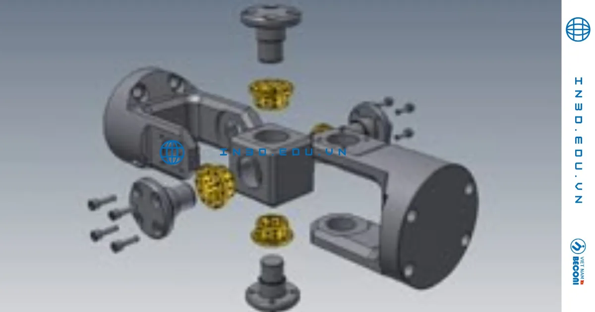
3D CAD Design Service at a Glance
| Design disciplines | Engineering/mechanical CAD (parametric) and artistic modeling (digital sculpting) |
|---|---|
| Accepted inputs | Hand sketches, 2D drawings, specifications, physical samples, reference photos, concept art |
| Engineering deliverables | STEP, IGES, native CAD files, 2D manufacturing drawings |
| Artistic deliverables | STL, OBJ, 3MF – split, keyed and hollowed for printing when needed |
| Target processes | FDM, SLA, DLP, SLS/MJF, SLM metal printing, CNC machining, injection molding |
| Pre-delivery checks | Units, solid/watertight geometry, wall thickness, assembly clearances, file versioning |
| File ownership | Delivered files belong to the customer once payment is complete; NDA available |
Two Design Disciplines, Two Different Toolsets
Customers often simply say “3D drawing”, but technically these are two distinct crafts. Choosing the wrong approach at the start leads to a file that looks great but cannot be manufactured – or one that can be manufactured but loses its character.
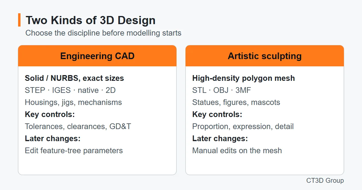
| Criteria | Engineering design (CAD) | Artistic design (sculpting) |
|---|---|---|
| Data type | Solid/NURBS with precise dimensions | High-density polygon mesh |
| Typical parts | Equipment housings, jigs & fixtures, mechanisms, mating parts | Statues, figures, mascots, reliefs, trophies, jewelry |
| Delivery formats | STEP, IGES, native files, 2D drawings | STL, OBJ, 3MF |
| Later modifications | Change parameters in the feature tree | Manual edits on the mesh |
| Key controls | Tolerances, assembly clearances, GD&T | Proportions, expression, detail sharpness |
Source: CT3D’s classification of design work.
Scope of Work: Engineering & Mechanical CAD Design
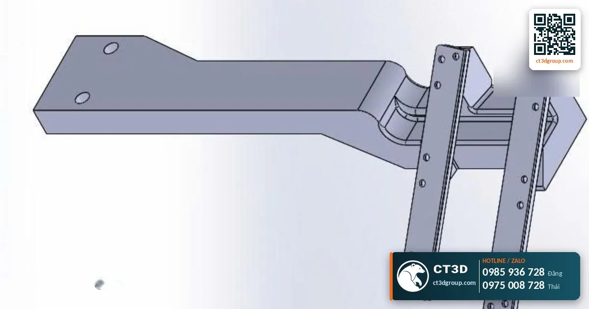
For engineering projects, CT3D engineers work from hand sketches, 2D drawings, specifications or physical samples. The scope includes:
- Single parts and assemblies: with mates, interference checks and basic motion simulation.
- Enclosure design: stiffening ribs, screw bosses, snap-fits and uniform wall thickness for injection molding or 3D printing.
- Production tooling: 3D printed jigs, fixtures and gauges as an alternative to machined metal – see our article on 3D printed jigs & fixtures.
- Manufacturing drawings: views, sections, dimensional and geometric tolerances, surface roughness requirements.
Scope of Work: Artistic Modeling
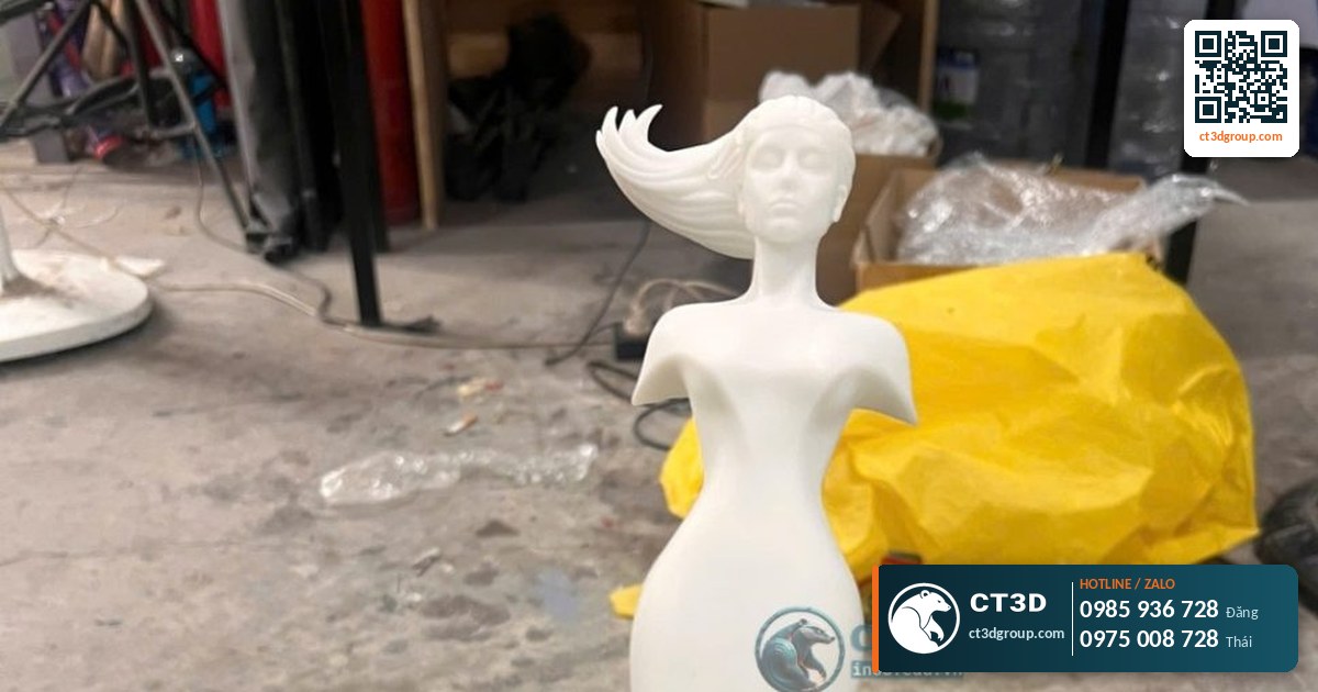
Artistic projects start from reference photos, sketches or concept art. Our 3D artists sculpt the overall form first, then add detail: drapery folds, facial features and ornamentation. Before export, the model is split into sections to fit the build volume, registration keys are added for precise assembly, and the model is hollowed with resin drain holes to save material. Published CT3D projects such as a 1 m tall Catholic statue printed in SLA and a giant Ca Mau shrimp model both went through this splitting and keying process.
How Our 3D Design Workflow Works

- RFQ: send photos, drawings, key dimensions, expected quantities and the preferred manufacturing process (if known).
- Requirements analysis and preliminary DFM: our engineers choose the design discipline, recommend a production process and flag risks (thin walls, overhangs, features that are too small).
- Quotation: based on estimated modeling hours and complexity, with a schedule. Market rates for simple model files start at around 200,000 VND (≈ US$8) – this is a general market reference, not CT3D’s price; all pricing is indicative and CT3D quotes per file.
- Modeling and milestone reviews: renders or 3D viewer files are shared at the blocking, detailing and finishing stages so you can give feedback early.
- Pre-production checks: wall-thickness analysis, watertight mesh check and assembly check.
- Delivery and prototyping: files are exported; if ordered, we move directly to 3D printing, CNC machining and painting in our own workshop.
File Standards and Target Manufacturing Processes
A design file is only valuable if it matches the manufacturing process behind it. CT3D applies design thresholds based on our workshop’s process data:
| Target process | Layer height | Typical tolerance | Design notes |
|---|---|---|---|
| FDM | 100–300 microns | ±0.1–0.3 mm | Avoid overhangs beyond 45°, larger minimum fit clearance |
| SLA | 25–100 microns | ±0.05–0.1 mm | Hollowing, resin drain holes, details down to 0.05 mm |
| DLP | 25–100 microns | ±0.03–0.08 mm | Ideal for small parts, jewelry, dental |
| SLS / MJF PA12 | 80–120 microns | ±0.05–0.15 mm | No supports needed; hollow parts need powder escape holes |
| SLM metal | — | ±0.02 mm | Self-supporting angles, machining allowance, 250×250×300 mm build volume |
Source: CT3D technology documentation 2026. Actual tolerance depends on geometry and print orientation.
More detail on assembly clearances is available in our article on accuracy & tolerances in 3D printing. See also our 3D printing services and metal 3D printing (SLM).
Design Guidelines We Apply to Every Model
The checks below are general design-for-manufacturing practice. Exact values depend on the material, part size and process, so treat the figures as typical starting points rather than fixed limits; our engineers confirm them for your part.
| Feature | Typical guidance | Why it matters |
|---|---|---|
| Wall thickness | Keep walls uniform; very thin walls (typically under about 1 mm in resin or 1.5–2 mm in FDM) need review | Thin or uneven walls warp, break or fill poorly in molds |
| Assembly clearance | Size gaps to the process tolerance – larger for FDM than for SLA or DLP | Parts that are modeled “line-on-line” will not assemble |
| Overhangs | Stay within about 45° from vertical for FDM, or plan supports | Unsupported overhangs sag and leave rough surfaces |
| Hollow parts | Add drain holes for resin or escape holes for powder | Trapped resin or powder adds weight and can crack the part |
| Internal corners for CNC | Use a corner radius at least equal to the cutting tool radius | Sharp internal corners cannot be milled directly |
| Molded parts | Add draft angles (typically 1–2°) and keep wall thickness consistent | Prevents sticking, sink marks and warpage in the mold |
| Embossed and engraved text | Keep characters bold and not too shallow for the chosen process | Fine text disappears in coarse layers or after sanding |
| Large models | Split to fit the build volume and add registration keys | Keys make sections line up accurately when bonded |
What You Receive
| Deliverable | Contents | Typical use |
|---|---|---|
| STEP / IGES | Neutral solid or surface model | Opening in any CAD/CAM system, CNC quoting, mold design |
| Native CAD file | Model with feature tree | Further parametric changes by your team |
| 2D drawings | Views, sections, tolerances, surface roughness | Machining orders and quality acceptance |
| STL / OBJ / 3MF | Watertight mesh, split and keyed if needed | 3D printing, artistic CNC, rendering |
| Renders / 3D viewer file | Milestone previews | Approvals, presentations, investor decks |

Supporting Hardware Startups
Startup teams often have great ideas but no mechanical engineers. CT3D supports them with a rapid prototyping loop: model the first version, print it in FDM to check dimensions and ergonomics, revise, then print in resin or PA12 for an appearance model to show investors. As volumes grow, the file is adapted with DFM for injection molding. Our article 3D printing vs. injection molding helps you decide the right moment to switch.
Industry Applications
- Electrical & electronics: control box enclosures, PCB brackets, sensor covers.
- Manufacturing plants: assembly fixtures, guide chutes, quick-replacement parts.
- Advertising & events: mascots, 3D logos, display models.
- Religious & fine art: statues, reliefs, devotional objects.
- Education: teaching models, engineering and architecture student projects.
Which Design Route Fits Your Project?
| Your starting point | Best route | Typical output |
|---|---|---|
| Drawings, sketches with dimensions or clear specifications | 3D CAD design (this service) | STEP/IGES, native files, 2D drawings or print-ready STL |
| A physical part with no drawings | Reverse engineering | CAD rebuilt from 3D scan data and measurements |
| Only an idea, a description or reference photos | Concept to 3D design | Model developed through massing renders and a printed test sample |
| An object to capture as it is | 3D scanning | Point cloud or watertight mesh |
Quality Control
Before delivery, every file goes through a checklist: correct units (mm), solid or watertight mesh, no inverted normals, wall thickness meeting the target process threshold, agreed assembly clearances, and clear file naming and versioning. For engineering projects, CT3D recommends printing a first-article inspection (FAI) sample to confirm real-world assembly before investing in tooling or metal machining.

How to Order a 3D Design
- Send your brief. Sketches, drawings, photos or a sample, plus key dimensions, quantity and the intended manufacturing process – through the Contact form, email or Zalo.
- Receive a quote with a free manufacturability review. We confirm the design discipline, flag risks and estimate modeling time and schedule.
- Review milestones. Approve renders at the blocking, detailing and finishing stages.
- Get your files – and a prototype if you want one. Files are delivered in the agreed formats; printing, CNC and painting can follow in our workshop.
Why Work with CT3D
- Engineers and 3D artists in one team – mechanical CAD and digital sculpting handled by the right specialist.
- Designed for the real process. Thresholds come from our own workshop’s process data for FDM, SLA, DLP, SLS/MJF and SLM.
- From file to part in one place. 3D printing, CNC machining, mold making and painting are done in-house.
- Early feedback. Milestone renders reduce costly late changes.
- Your files, your IP. Ownership transfers on payment; NDA on request; engineering support in English.
Frequently Asked Questions
I only have photos. Can you still create a 3D design?
Yes, for artistic models. For engineering parts we need at least a few key dimensions or a physical sample to guarantee proper fit.
Who owns the design files?
Delivered files belong to the customer once payment is complete. CT3D can sign a non-disclosure agreement (NDA) for new product projects.
How long does it take to get the files?
It depends on complexity. The general market lead time for jobs that require modeling plus printing is 3–7 days; CT3D confirms a specific schedule when we receive your request.
Do you fix files made by others?
Yes. Our engineers will check the file and report the issues and proposed fixes before quoting.
Which file formats will I receive?
Engineering projects are delivered as STEP or IGES, with native CAD files and 2D drawings when ordered. Artistic models are delivered as STL, OBJ or 3MF, split and keyed for printing if required. Tell us which software your team uses and we will export accordingly.
Can you prepare 2D manufacturing drawings?
Yes. Drawings can include views, sections, dimensional and geometric tolerances and surface roughness requirements, ready for machining orders or quality acceptance.
Do you design for injection molding?
Yes. Enclosures are designed with uniform wall thickness, ribs, screw bosses and snap-fits, and files can be adapted with DFM for injection molding as volumes grow. Many customers validate the design with 3D printed prototypes first.
Can you also make the prototype?
Yes. Once the files are approved, CT3D can 3D print, CNC machine and paint the part in our own workshop, so you can check fit and appearance before investing in tooling.
See also: our guide to 3D modeling costs for printing, our concept to 3D design service and our reverse engineering service.
Watch: Real Footage from the CT3D Workshop
Watch the video 3D Scanning Service – CT3D Scan 3D to see our process and output quality first-hand. More videos are available on our channel Che Tao Vlog – CT3D (in Vietnamese).
Contact CT3D – Send Your Files for a Fast Quote
Whether you have a 3D file, 2D drawings, photos or just an idea, you can send it to CT3D. Our engineers will review your files (STL, STEP, IGES, OBJ), advise on technology and materials, and send a quotation with the delivery schedule.
- Email: [email protected] – [email protected]
- Phone / Zalo: +84 975 008 728 (Mr. Thai) – +84 985 936 728 (Mr. Dang), or use our Contact form
- Head office: Binh Duong, Vietnam.
- Workshops: Ho Chi Minh City, Vietnam (three locations).
- Other workshops and drop-off points: Can Tho, Da Nang, Bien Hoa, Ba Ria – Vung Tau, Hanoi, Hai Duong, Hai Phong. Nationwide delivery within Vietnam; international shipping on request.
- Website: ct3dgroup.com – in3d.edu.vn
CT3D – 3D design & prototyping: 3D printing, 3D scanning, reverse engineering, silicone mold making, painting & finishing, CNC machining, composite fabrication, plus 3D printers and 3D printing resins.
Have a Part or Product to Design?
Send your sketches, drawings, photos or sample with the key dimensions and target process. Our engineers will review manufacturability and reply quickly with a quotation.