
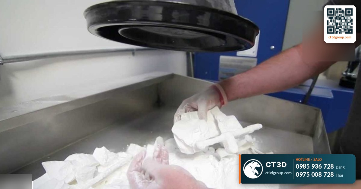
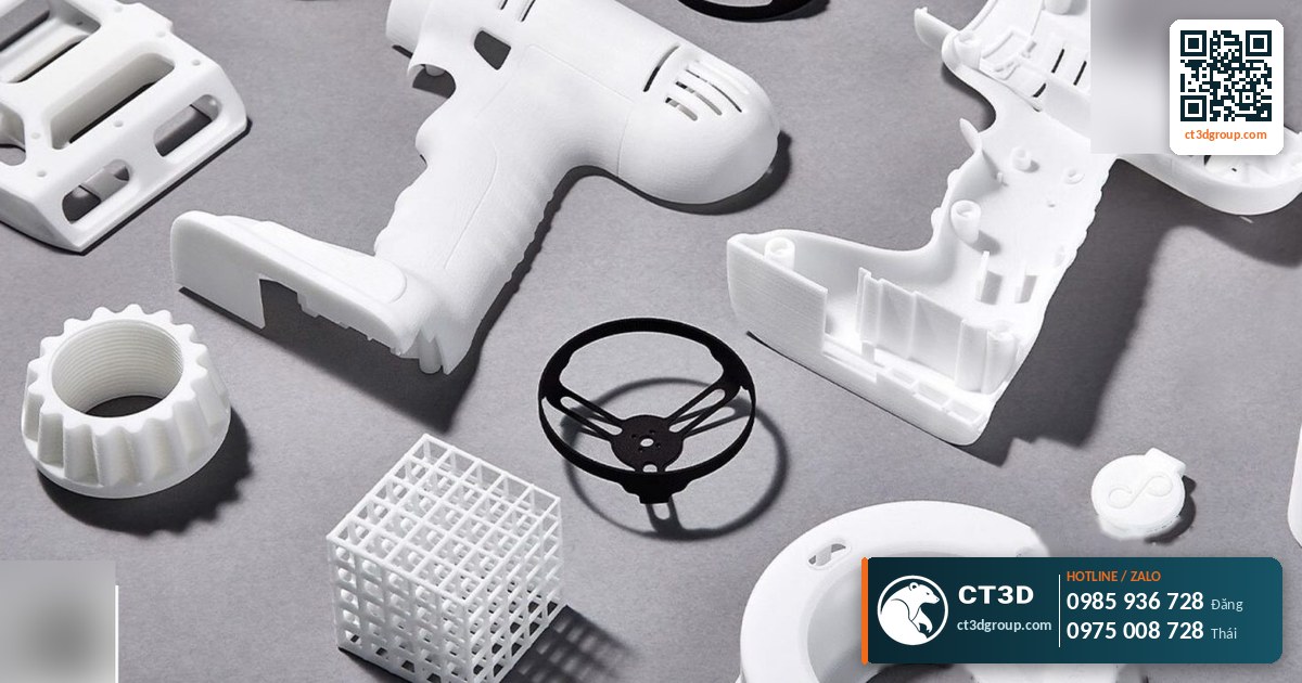
Quick answer: In the MJF vs SLS comparison, both are powder-based plastic 3D printing technologies (usually PA12) that need no supports and produce functional parts with mechanical properties close to injection-molded plastic. SLS uses a CO2 laser that scans point by point, with layers of about 80–120 micron and a tolerance of ±0.05–0.15 mm. MJF uses inkjet heads to apply a fusing agent and an infrared lamp to fuse a whole layer at once, achieving a tolerance of about ±0.05 mm and a smoother, more uniform surface that suits batch production. SLS has the edge when you need a natural white color or specialty materials.
Engineers often ask me: “Should this PA12 part be printed in MJF or SLS?” Parts from the two technologies look quite similar, since both are sintered plastic powder, but the way each layer is formed is completely different, so accuracy, surface finish, color and efficiency at volume also differ. This article goes into the technical details so you can choose correctly. For an overview of FDM, SLA, MJF and SLM, see CT3D’s pillar article on 3D printing technologies.
What are MJF and SLS? How do their principles differ?
Both belong to the powder bed fusion family. The machine spreads a thin layer of plastic powder across the build platform, melts the areas to be kept, lowers the platform and spreads the next layer. Unfused powder stays around the part and supports it. That is why neither MJF nor SLS needs support structures like FDM or resin (see 3D printing supports explained).
SLS – laser sintering
SLS (Selective Laser Sintering) uses a CO2 laser. Scanning mirrors steer the beam to trace the part’s cross-section on the powder layer. Wherever the beam passes, powder particles melt and fuse together. The build chamber is preheated to just below the powder’s melting point, so the laser only needs to add a little extra energy. Because the laser traces line by line, the time per layer increases with cross-sectional area: the more geometry in a layer, the longer it takes.
MJF – fusing agent and infrared fusion
MJF (Multi Jet Fusion) does not use a laser. An inkjet-style print head array passes over the powder layer and jets two liquids: a fusing agent (a black, heat-absorbing agent) onto areas to be melted, and a detailing agent (a cooling agent) along the edges to keep them sharp. An infrared lamp then sweeps across the entire layer. Areas with fusing agent absorb more heat and melt; the rest does not. Because the whole layer is fused at once, the time per layer is almost independent of how many parts are on the bed.
The direct consequence: MJF maintains a consistent speed when the build chamber is fully packed, making it ideal for low-volume production. SLS is more flexible in materials and colors, but slows down with large cross-sections.

MJF vs SLS technical specifications compared
| Criterion | MJF (PA12) | SLS (PA12) |
|---|---|---|
| Energy source | Infrared lamp + fusing agent | CO2 laser |
| Layer formation | Entire layer fused at once | Scanned line by line along the cross-section |
| Layer thickness | About 80 micron | 80–120 micron |
| Dimensional tolerance | About ±0.05 mm | ±0.05–0.15 mm |
| Supports | Not needed | Not needed |
| Natural color | Dark gray (from the fusing agent), usually dyed black | Off-white, easy to dye in many colors |
| Surface | Smooth, uniform grain, minimal roughness | Slightly rough, like fine sandpaper |
| Z-axis mechanical properties | More uniform across directions | Z direction usually weaker than X and Y |
| Common materials | PA12, PA11, TPU (machine dependent) | PA12, PA11, glass-filled PA, TPU |
| Best for | Low-volume batches, black functional parts | One-offs, light colors or specialty materials |
Source: CT3D technical documentation (SLS 80–120 micron layers, ±0.05–0.15 mm; MJF/MJP PA12 ±0.05 mm) and general technology characteristics.
In-depth analysis: choosing MJF or SLS based on part requirements
Accuracy and fine detail
With SLS, the laser spot size and powder clinging around the edges make edges slightly rounded and small holes tend to close up. MJF uses a detailing agent to cool the edges, so the boundary between fused and unfused areas is sharper. In practice, if a part has fit holes, snap-fits or small teeth, I usually favor MJF because of its tolerance of about ±0.05 mm. With SLS, you should allow a wider tolerance, about ±0.1 mm or more, on mating surfaces. I cover how to design assembly clearances in a separate article on 3D printing accuracy and tolerances.
Mechanical properties and isotropy
“Isotropic” means a part carries load equally in all directions. FDM is highly anisotropic because the printed layers bond weakly. SLS is much better, but the Z direction (stacking direction) is still usually slightly weaker, with lower elongation at break. MJF fuses the whole layer with uniform heat, so each layer bonds well into the previous one and properties are closer across directions. For parts subject to bending, impact or with living hinges, MJF typically gives more consistent results from batch to batch.
Surface and finishing
SLS parts come off the machine off-white with a slightly matte, rough surface. The upside is that they can be dyed many colors (red, blue, yellow, etc.) and are easy to paint. MJF parts are dark gray because the black fusing agent soaks in, so they are almost always dyed black or painted in dark colors. In return, the MJF surface is smoother and more uniform, and after bead blasting looks very much like injection-molded plastic. If the product needs a native white or light color, SLS is the more sensible choice.
Productivity at volume
This is the biggest difference. With MJF, print time depends mainly on the build height used, not much on the number of parts per layer. So when you nest dozens or hundreds of small parts in one build, the cost per part drops noticeably. With SLS, the laser has to trace every cross-section, so more parts mean more scanning time. For 1–5 parts the difference is small; for dozens to hundreds of identical parts, MJF usually has the advantage. For volume discounts, see high-volume 3D printing and low-volume production.
Estimating cost: look at the bounding volume, not just the weight
With powder technologies, cost is not calculated only by the grams of finished plastic. The powder surrounding the part is heated throughout the build and only partly reusable. So a large but hollow part (a thin-walled box) still occupies a lot of build volume. A simple way to think about it: Cost ≈ (part volume × material unit price) + (build height occupied × machine-hour rate ÷ number of parts in the build) + post-processing. MJF and SLS have no fixed public prices on the market, so CT3D quotes based on your file after our engineers calculate volume and build packing.
What should you consider when designing files for MJF and SLS?
| Design feature | General recommendation | MJF / SLS notes |
|---|---|---|
| Wall thickness | About 1 mm or more; 2 mm for load-bearing parts | Walls that are too thin warp easily, especially on long parts |
| Powder escape holes | Enclosed hollow parts need at least 2 holes a few mm in diameter | Without holes, trapped powder cannot be removed |
| Assembly clearance | 0.3–0.5 mm for moving fits | MJF can use smaller clearances than SLS |
| Embossed and engraved text | Minimum height/depth of about 0.5 mm | Small text on SLS can blur due to clinging powder |
| Large flat surfaces | Add stiffening ribs, avoid thick solid plates | Reduces warping from shrinkage during cooling |
Source: general design guidelines for PA12 powder technologies, CT3D engineering experience.
One point often overlooked: very thick solid sections store a lot of heat and cool more slowly than thin areas, causing uneven shrinkage and warping. I usually advise hollowing out or ribbing sections thicker than 10 mm, and remembering to leave powder escape holes.
Common MJF and SLS defects and how to fix them
- Warping on long, flat parts: caused by uneven shrinkage during cooling. Fix by adding ribs, splitting the part, or tilting it in the build chamber.
- Powder trapped in enclosed cavities: caused by missing escape holes. Fix by adding 2 holes at opposite ends of the cavity, large enough for compressed air to blow the powder out.
- Small holes closing up, shafts not fitting: caused by powder clinging to edges. Fix by compensating dimensions in CAD or reaming holes after printing.
- “Orange peel” surface on SLS: usually caused by powder reused too many times. The shop must control the ratio of fresh to recycled powder.
- Uneven color on MJF: thick and thin areas show different shades of gray. Fix by dyeing black after printing for a uniform color.
- Unusually brittle parts: possibly due to thermally aged material or sharp corners concentrating stress. Use internal fillets of at least 0.5–1 mm.
When to choose MJF and when to choose SLS: a decision checklist
Here is a quick checklist you can run through before sending your file:
- Does the part need to be white or a light color? Yes → favor SLS. No → continue.
- Are there tight fits, snap-fits or small threads? Yes → favor MJF for its tolerance of about ±0.05 mm.
- Quantity of several dozen parts or more? Yes → MJF is usually more economical because it fuses whole layers.
- Need a specialty material such as glass-filled PA? Yes → check SLS availability.
- Multi-directional loads or impact? MJF is usually more uniform; SLS still performs well with sound design.
- Is cosmetic appearance important? MJF + bead blasting + black dyeing gives a surface close to injection-molded plastic.
If you are unsure, just send a STEP or STL file. CT3D engineers will review the geometry, quantity and fit requirements and recommend the right technology, sometimes combining both: SLS for white presentation models and MJF for batches of functional parts.
CT3D’s MJF/SLS printing process
- Send your file: STL, STEP, OBJ or 3MF via our website, Zalo or email.
- Technical requirements: quantity, color, mating surfaces, operating environment (heat, oil, outdoor).
- Engineering file review: check wall thickness and powder escape holes, calculate volume and build packing.
- Quote with lead time: quoted per file, stating whether MJF or SLS is recommended and why.
- Production: printing, cooling, depowdering, bead blasting, dyeing or painting if required.
- Delivery: pickup at the workshop or nationwide delivery within 1–3 days of completion.
You can also see the PA12 3D printing service page on in3d.edu.vn and CT3D’s multi-technology, multi-material 3D printing service.
Real-world applications of MJF and SLS
Low-volume electronics enclosures: housings with snap-fits and screw bosses that need a uniform black finish. MJF is a good fit thanks to its smooth surface, tight tolerance and ability to print many housings in one build.
Air ducts and complex conduits: multi-axis curved ducts with thin internal walls. Powder technologies need no supports, so they can print shapes that are difficult in FDM or resin. Both MJF and SLS work; choose based on color and quantity.
Jigs, clamps and production line parts: PA12 is durable, reasonably resistant to oil and grease, and more impact resistant than standard resin. I cover fixtures in detail in 3D printed jigs and fixtures.
Light-colored presentation models: products that need to be white or dyed in brand colors. SLS has the advantage because its base powder is white.
Living hinges and flexible parts: PA12 has some flexibility; thin hinges printed in MJF usually last longer under repeated flexing. For rubber-like elasticity, consider powder TPU.
Compared with other technologies, if you only need a single appearance model with a very smooth finish, SLA resin may be cheaper and better looking. If you need multiple functional, load-bearing parts, MJF/SLS is the right direction. For the full comparison table of methods, go back to our article on 3D printing technologies.
Frequently asked questions
Which is stronger, MJF or SLS?
With the same PA12 material, the tensile strength of the two technologies is quite close. MJF is usually more uniform across directions and between batches, while SLS may be slightly weaker in the Z direction.
Why are MJF parts dark gray?
Because MJF jets a black fusing agent onto the areas to be fused. The agent soaks into the plastic, so parts come off the machine gray and are usually dyed black for a uniform color.
Do MJF or SLS prints need supports?
No. The unfused powder surrounding the part supports it, so complex shapes, nested parts and curved ducts can be printed without supports.
How much does MJF and SLS printing cost?
MJF and SLS have no fixed public price lists on the market. Price depends on part volume, build height occupied, quantity and post-processing, so CT3D quotes based on your file.
What is the tolerance of MJF printing?
According to CT3D documentation, MJF/MJP PA12 printing achieves about ±0.05 mm; SLS about ±0.05–0.15 mm depending on part size and geometry.
Real footage from the CT3D workshop
Watch the video Metal, SLA, MJP lost-wax and PA12 3D printing by CT3D to get a clearer picture of the process and product quality. More videos are available on the Che Tao Vlog – CT3D channel.
Contact CT3D – send your file, get a fast quote
Whether you have a 3D file, a 2D drawing, photos or just an idea, you can send it to CT3D. Our engineers will check the file, advise on technology and materials, and send a quote with a delivery time.
- Email: [email protected] – [email protected]
- Hotline / Zalo: +84 975 008 728 (Mr. Thai) – +84 985 936 728 (Mr. Dang), or use our contact form
- Head office: Binh Duong.
- Workshops in Ho Chi Minh City: Linh Trung (Thu Duc), Tam Binh (Thu Duc), District 6 (former).
- Other workshops and drop-off points: Can Tho, Da Nang, Bien Hoa, Ba Ria – Vung Tau, Hanoi, Hai Duong, Hai Phong. Nationwide delivery.
- Website: ct3dgroup.com – in3d.edu.vn
CT3D – 3D design & prototyping: 3D printing, 3D scanning, reverse engineering, silicone mold making, paint finishing, CNC machining, composite fabrication, and supply of 3D printers and 3D printing resins.
Danh sách cửa hàng:
CT3D là đơn vị cung cấp trọn gói các dịch vụ thiết kế và sản xuất theo yêu cầu tại TP.HCM và khu vực lân cận (Bình Dương, Đồng Nai, Long An…). Với năng lực khép kín từ thiết kế 3D, in 3D (FDM, resin/SLA, SLS, in 3D kim loại), scan 3D – thiết kế ngược, làm khuôn, đúc composite – poly resin – poly stone đến gia công CNC và sơn màu hoàn thiện, CT3D đồng hành cùng khách hàng qua toàn bộ quy trình – từ ý tưởng, bản vẽ hay sản phẩm mẫu đến thành phẩm hoàn chỉnh. Dù bạn cần tạo mẫu nhanh, sản xuất số lượng, chế tác tượng – mô hình – quà tặng hay linh kiện kỹ thuật, đội ngũ CT3D sẽ tư vấn công nghệ và vật liệu phù hợp, đảm bảo sản phẩm sắc nét, đúng yêu cầu và tối ưu chi phí. Khách hàng tại TP.HCM và vùng lân cận có thể trao đổi trực tiếp, gửi file online và nhận sản phẩm thuận tiện, hỗ trợ cả đơn gấp lẫn dự án số lượng.
CT3D cung cấp trọn gói các dịch vụ thiết kế và sản xuất theo yêu cầu, phục vụ khách hàng tại Hà Nội và các tỉnh lân cận (Bắc Ninh, Hưng Yên, Hải Phòng, Vĩnh Phúc…). Với năng lực khép kín từ thiết kế 3D, in 3D (FDM, resin/SLA, SLS, in 3D kim loại), scan 3D – thiết kế ngược, làm khuôn, đúc composite – poly resin – poly stone đến gia công CNC và sơn màu hoàn thiện, CT3D đồng hành cùng khách hàng qua toàn bộ quy trình – từ ý tưởng, bản vẽ hay sản phẩm mẫu đến thành phẩm hoàn chỉnh. Quy trình làm việc thuận tiện: bạn gửi file 3D hoặc mô tả ý tưởng qua online, đội ngũ CT3D tư vấn công nghệ – vật liệu, báo giá nhanh và giao hàng tận nơi tại Hà Nội. Dù bạn cần tạo mẫu nhanh, sản xuất số lượng, chế tác tượng – mô hình – quà tặng hay linh kiện kỹ thuật, CT3D đều đáp ứng với sản phẩm sắc nét, đúng yêu cầu và tối ưu chi phí.

