
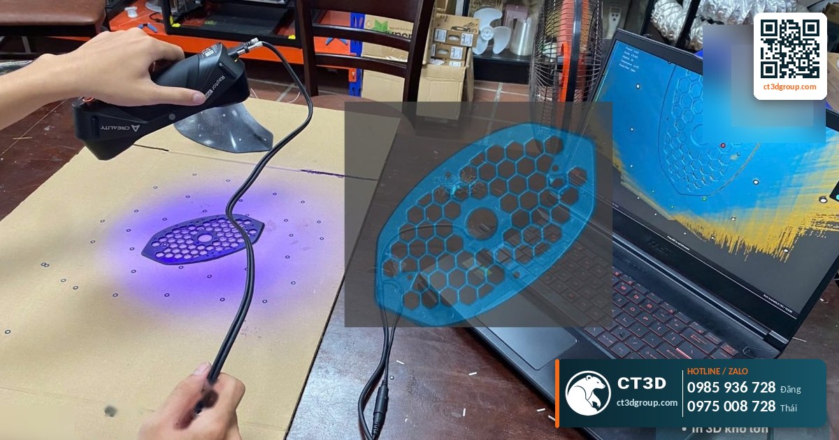
Quick answer: Reverse engineering is the process of working backward from a physical object to a design file. Instead of drawing first and then manufacturing, you measure or 3D scan an existing object, then rebuild a clean CAD model (STEP or IGES files, 2D drawings) for CNC machining, 3D printing or mold making. The process has 5 steps: data capture → scan data processing → CAD modeling → deviation check → trial production. Main applications: remaking discontinued spare parts, improving products, and restoring statues.
This is a beginner’s overview of the reverse engineering concept. If you need to remake a machine part, see our in-depth article on spare part recovery with 3D scanning and metal printing. For statues and reliefs, see statue restoration with 3D scanning.
What is reverse engineering? Explained in one minute
Conventional manufacturing runs forward: idea → drawing → product. Reverse engineering runs the other way: existing product → drawing.
An everyday example: you have a broken plastic cover from an old machine. The manufacturer no longer sells it, and nobody has the drawing. An engineer measures the cover (with calipers or a 3D scanner), rebuilds it as a 3D file in software, repairs the broken area, and then 3D prints or machines a new cover. That is reverse engineering.
Reverse engineering is not simply “copying”. The engineer must understand the part’s function: which faces mate with which, which holes need to be precise, and where wear needs to be compensated. The final file is often more accurate than the physical part because distortion and wear have been removed.
Reverse engineering vs. 3D scanning
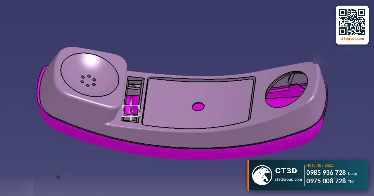
These two terms are often used interchangeably. In fact, 3D scanning is just one step in reverse engineering.
| Criterion | 3D scanning | Reverse engineering |
|---|---|---|
| Goal | Capture the surface shape of a real object | Create a clean design file for production |
| Output | Triangle mesh file (STL, OBJ) | Solid CAD file (STEP, IGES, native software file), 2D drawings |
| Editing dimensions | Difficult, because it is a triangle mesh | Easy, parameter by parameter |
| Use for CNC machining | Limited | Suitable |
| Use for 3D printing statues and models | Usually sufficient | Not required |
| Performed by | Scanning technician | Mechanical/CAD design engineer |
Source: compiled from CT3D’s workflow.
What are the steps in the reverse engineering process?
Below is the general process. Each project may add or skip steps depending on its purpose.
Step 1: Data capture
Simple parts (blocks, shafts, flanges) can be measured with calipers and micrometers. Parts with curved, complex surfaces are 3D scanned. The engineer also asks for additional information: what the original material was, what the part mates with, and what loads it carries.
Step 2: Scan data processing
Removing noise, aligning scans, filling holes and setting up the coordinate system. Only with a correctly placed coordinate system will the following steps be accurate.
Step 3: CAD modeling
The engineer redraws planes, cylinders, holes, ribs and so on, following the scan data. For freeform surfaces (vehicle bodies, handles, statues), NURBS surfaces can be built. Dimensions are rounded to sensible nominal values (for example, a hole measured at 9.96 mm is usually a worn 10 mm hole).
Step 4: Deviation check
The new CAD model is compared with the scan data. The software color-maps the deviations so the engineer knows where adjustments are needed. CT3D offers 3D inspection services, scan-to-CAD comparison and GD&T evaluation.
Step 5: Trial production and adjustment
A prototype is 3D printed in plastic for a test fit first. Only once it fits do we move to the final material (metal, engineering plastic). This saves a great deal compared with machining directly in metal and then discovering errors.
Reverse engineering terms beginners should know
- CAD: computer-aided design software and engineering design files.
- STEP / IGES: neutral CAD file formats that open in almost any software, used for CNC machining.
- Mesh / STL: triangle mesh files, the output of 3D scanning, well suited to 3D printing. See also what is an STL file.
- Nominal dimension: the standard design dimension, excluding tolerance.
- Tolerance: the allowable range of variation. Mating parts need clearly defined tolerances.
- GD&T: the system of geometric tolerance symbols such as flatness, concentricity and perpendicularity.
- Deviation color map: an image color-coding the differences between the scan and the CAD model.
Where is reverse engineering used?
Remaking discontinued machine spare parts
This is the most common application in factories. A gear, pump impeller, bushing or lever on imported machinery breaks. The manufacturer has stopped selling it, or ordering one takes a long time. Reverse engineering provides a file for CNC machining or metal 3D printing. According to CT3D’s documentation, SLM metal 3D printing achieves a tolerance of ±0.02 mm, can produce from a single part, and can cut spare part import costs by up to 40%. For the detailed process, see spare part recovery with 3D scanning and metal printing. To choose between metal printing and machining, see metal 3D printing vs. CNC.
Restoring and enlarging statues and reliefs
Damaged antique or devotional statues can be scanned, repaired digitally, and then remade by 3D printing or CNC. CT3D has restored the Our Lady of La Vang statue and a large reclining Buddha. See statue restoration with 3D scanning.
Improving existing products
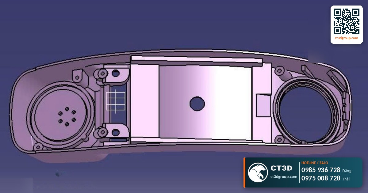
A company has an old product sample but no longer has the original file. Reverse engineering recovers the file, which can then be modified, improved and used to make new molds.
Designing form-fitting accessories
Jigs, brackets and protective housings need to fit snugly around an existing object. Reverse engineering captures the exact surface to design the mating parts.
Archiving technical records
Factories digitize critical parts so they can replace them proactively when needed, without depending on suppliers.
Things to watch out for when ordering reverse engineering
| Situation | Risk | How CT3D handles it |
|---|---|---|
| Heavily worn part | The file copies the wear too, leading to a loose fit | Engineers compensate for wear and restore nominal dimensions |
| Broken part with missing pieces | Missing data | Scan the fragments, cross-reference symmetrical features or mating parts |
| Unknown original material | Wrong material choice, new part fails quickly | Ask about operating conditions, recommend a substitute material |
| Precision mating parts | Poor fit | 3D print in plastic for a test fit before making it in the final material |
| Glossy, black or transparent surfaces | Difficult to scan | Apply scan spray, combine with manual measurement |
Source: hands-on experience of CT3D engineers.
Please also keep intellectual property in mind: reverse engineering should be used for your own parts, replacement parts for repair purposes, or when you have the right to use the design.
Checklist for sending a reverse engineering request to CT3D
- Photos of the part from multiple angles, with a ruler in frame to show scale.
- Purpose: 3D printing, CNC machining, mold making, inspection or archiving.
- What the part mates with and which faces are critical.
- Original material (if known) and operating conditions: temperature, load, environment.
- Quantity to be produced once the file is ready.
- Old drawings or manufacturer specifications (if available, even if incomplete).
CT3D’s workflow has 6 steps: send information → state technical requirements → engineering review → quote with lead time → confirmation and execution → delivery of files or parts, door-to-door or pickup at our workshop. Reverse engineering is quoted per part. For a reference on modeling costs, see 3D modeling costs. You can reach us via Zalo, email or our contact form.
Frequently asked questions
What is reverse engineering?
Reverse engineering means measuring or scanning an existing object and rebuilding a clean CAD file for production, modification or archiving.
Does reverse engineering always require 3D scanning?
No. Simple parts can be measured with calipers. 3D scanning is needed for curved, complex surfaces or when high overall accuracy is required.
What files do I receive after reverse engineering?
Usually STEP or IGES files, along with the native software file and 2D drawings if needed. STL can also be exported for 3D printing.
Can a broken part be reverse engineered?
In many cases, yes. Engineers scan the fragments and cross-reference mating parts or symmetrical features to rebuild it.
How long does reverse engineering take?
It depends on complexity. CT3D provides a specific lead time together with the quote after reviewing the part.
Real footage from the CT3D workshop
Watch the video 3D scanning service – CT3D Scan 3D by CT3D to get a clearer picture of the process and product quality. More videos on the Che Tao Vlog – CT3D channel.
Contact CT3D – send your files, get a fast quote
Whether you have a 3D file, a 2D drawing, photos or just an idea, you can send it to CT3D. Our engineers will review the file, recommend the right technology and material, and send you a quote with a lead time.
- Email: [email protected] – [email protected]
- Hotline / Zalo: +84 975 008 728 (Mr. Thai) – +84 985 936 728 (Mr. Dang), or use our contact form
- Head office: Binh Duong.
- Workshops in Ho Chi Minh City: Linh Trung (Thu Duc), Tam Binh (Thu Duc), former District 6.
- Other workshops and drop-off points: Can Tho, Da Nang, Bien Hoa, Ba Ria – Vung Tau, Hanoi, Hai Duong, Hai Phong. Nationwide delivery across Vietnam.
- Website: ct3dgroup.com – in3d.edu.vn
CT3D – 3D design & prototyping: 3D printing, 3D scanning, reverse engineering, silicone mold making, painting and finishing, CNC machining, composite fabrication, and supply of 3D printers and 3D printing materials.
Danh sách cửa hàng:
CT3D là đơn vị cung cấp trọn gói các dịch vụ thiết kế và sản xuất theo yêu cầu tại TP.HCM và khu vực lân cận (Bình Dương, Đồng Nai, Long An…). Với năng lực khép kín từ thiết kế 3D, in 3D (FDM, resin/SLA, SLS, in 3D kim loại), scan 3D – thiết kế ngược, làm khuôn, đúc composite – poly resin – poly stone đến gia công CNC và sơn màu hoàn thiện, CT3D đồng hành cùng khách hàng qua toàn bộ quy trình – từ ý tưởng, bản vẽ hay sản phẩm mẫu đến thành phẩm hoàn chỉnh. Dù bạn cần tạo mẫu nhanh, sản xuất số lượng, chế tác tượng – mô hình – quà tặng hay linh kiện kỹ thuật, đội ngũ CT3D sẽ tư vấn công nghệ và vật liệu phù hợp, đảm bảo sản phẩm sắc nét, đúng yêu cầu và tối ưu chi phí. Khách hàng tại TP.HCM và vùng lân cận có thể trao đổi trực tiếp, gửi file online và nhận sản phẩm thuận tiện, hỗ trợ cả đơn gấp lẫn dự án số lượng.
CT3D cung cấp trọn gói các dịch vụ thiết kế và sản xuất theo yêu cầu, phục vụ khách hàng tại Hà Nội và các tỉnh lân cận (Bắc Ninh, Hưng Yên, Hải Phòng, Vĩnh Phúc…). Với năng lực khép kín từ thiết kế 3D, in 3D (FDM, resin/SLA, SLS, in 3D kim loại), scan 3D – thiết kế ngược, làm khuôn, đúc composite – poly resin – poly stone đến gia công CNC và sơn màu hoàn thiện, CT3D đồng hành cùng khách hàng qua toàn bộ quy trình – từ ý tưởng, bản vẽ hay sản phẩm mẫu đến thành phẩm hoàn chỉnh. Quy trình làm việc thuận tiện: bạn gửi file 3D hoặc mô tả ý tưởng qua online, đội ngũ CT3D tư vấn công nghệ – vật liệu, báo giá nhanh và giao hàng tận nơi tại Hà Nội. Dù bạn cần tạo mẫu nhanh, sản xuất số lượng, chế tác tượng – mô hình – quà tặng hay linh kiện kỹ thuật, CT3D đều đáp ứng với sản phẩm sắc nét, đúng yêu cầu và tối ưu chi phí.

