
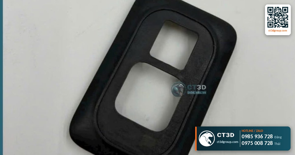
Quick answer: SLS 3D printing (Selective Laser Sintering) uses a laser to scan a layer of preheated plastic powder, melting the particles in the scanned area so they fuse into a solid. According to CT3D’s technical documentation, SLS prints at 80–120 micron layers with a tolerance of ±0.05–0.15 mm and needs no supports. The most common material is nylon PA12. SLS is well suited to durable engineering parts, complex geometries and low-volume production. SLS pricing: quoted per file.
When customers ask CT3D about plastic parts that are “ready to use straight off the printer,” SLS is usually on the shortlist. But many people confuse SLS with SLA (resin printing) or SLM (metal printing) because the names are so similar. This article explains how laser sintering works, the thermal parameters that determine quality, and how to design for SLS. For an overview of all technologies, see our pillar article on 3D printing technologies.
What Is SLS 3D Printing? SLS vs. SLA vs. SLM
These three technologies have similar names but completely different materials and mechanisms:
| Technology | Feedstock | Energy source | Mechanism |
|---|---|---|---|
| SLS | Plastic powder (PA12, PA11…) | Laser | Heats the powder until particles melt and fuse together |
| SLA | Liquid photopolymer (resin) | UV laser | A photochemical reaction solidifies the resin |
| SLM | Metal powder | High-power laser | Fully melts the metal powder |
Source: CT3D technical summary.
In short: SLS is “laser printing with plastic powder.” If you need metal parts, see metal 3D printing; if you need resin, see what is SLA 3D printing.
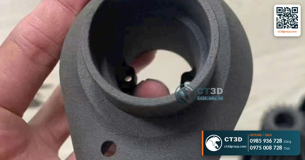
How Does Laser Sintering Work?
Step 1: Heat the build chamber
Before printing, the entire build chamber and powder bed are heated to just below the powder’s melting point. That way, the laser only needs to add a small amount of energy to melt the powder. If the chamber is cold, the temperature difference between the freshly scanned area and its surroundings is too large, and the part shrinks heavily and warps during the print.
Step 2: Spread the powder
A recoater blade or roller spreads a thin, even layer of powder exactly as thick as the selected layer height, in the 80–120 micron range.
Step 3: The laser scans the cross-section
The laser beam is steered by scanning mirrors along the outline of the layer’s cross-section. For plastics, industrial SLS machines usually use a CO2 laser because plastics absorb its wavelength well. Wherever the laser passes, the powder particles melt and bond to neighboring particles and to the layer below.
Step 4: Lower the platform and repeat
The build platform drops by one layer, the recoater spreads fresh powder, and the laser scans again. Unscanned powder stays in place, surrounding and supporting the part – which is why SLS needs no supports.
Step 5: Controlled cooling
After printing, the block of powder (the “powder cake”) containing the parts must cool slowly inside the machine or in a cooling station. Many people leave this step out when estimating lead times, but cutting it short is a common cause of warping.
The “Thermal Window”: The Most Important Concept in SLS
Semi-crystalline plastics such as PA12 have two key temperatures: the melting point (on heating) and the crystallization temperature (on cooling). There is a gap between them, called the sintering window. The chamber is held within this window so that freshly melted areas don’t crystallize immediately, stay “soft” long enough for the next layer to fuse to them, and the whole part shrinks evenly as it cools together.
That is why not every plastic can be printed with SLS. The material needs a wide enough thermal window and a suitable particle size. PA12 meets these requirements well, which is why it has become the workhorse material of SLS.
Laser energy: too little or too much both cause problems
- Too little energy: particles only bond at the surface, leaving the part porous, brittle and noticeably weaker.
- Too much energy: heat spreads into neighboring powder, which sticks to the part, making dimensions grow, small holes close up and edges lose their sharpness.
Energy depends on laser power, scan speed, hatch spacing and layer height. Machine operators must balance these factors for each powder type.
SLS 3D Printing Specifications
| Parameter | Value | Notes |
|---|---|---|
| Layer height | 80–120 microns | Thinner layers give a smoother surface |
| Dimensional tolerance | ±0.05–0.15 mm | Depends on part size and geometry |
| Supports | Not required | Unsintered powder supports the part |
| Surface | Fine matte, slightly grainy | Can be bead-blasted, dyed or painted |
| Natural PA12 color | Off-white | Can be dyed in many colors |
| Price | Quoted per file | No published market prices |
Source: CT3D technical documentation.
Which Materials Can Be Used for SLS?
- PA12: the most common material, balancing strength, toughness, dimensional stability and chemical resistance.
- PA11: bio-based, more ductile and more impact-resistant, suitable for hinges and flexing parts.
- Glass-bead or fiber-reinforced PA: stiffer and more thermally stable, but more brittle.
- TPU powder: rubber-like elasticity for pads, gaskets and shock-absorbing parts.
At CT3D, our powder-bed plastic technologies run PA12 via MJF/SLS. The detailed differences between these two powder technologies are covered in MJF vs. SLS and MJF PA12 3D printing.
Design Guidelines for SLS Parts
Thin walls and small features
Walls that are too thin warp easily as they cool and break easily during depowdering. A common recommendation is a wall thickness of about 1 mm or more; long, tall walls should be thicker or ribbed.
Hollow parts need powder escape holes
If you hollow out a part to save weight, the powder inside will be trapped unless it has a way out. You need at least two escape holes so air can be blown in and powder poured out.
Clearance for print-in-place assemblies
SLS can print moving assemblies in one piece, such as hinges, chains and swivel joints. The gap between surfaces must be large enough, usually about 0.5 mm or more, so that the powder in the gap can be cleared and the two surfaces don’t sinter together.
Avoid solid, bulky sections
Thick sections hold heat for a long time and cool more slowly than the thin walls next to them, causing uneven shrinkage and sink marks. The solution is to core them out or use ribs or an internal lattice.
To choose clearances for press fits, sliding fits and loose fits, see accuracy and tolerances in 3D printing.
Common SLS Printing Problems and How to Fix Them
| Problem | Cause | Fix |
|---|---|---|
| Warping on large flat surfaces | Uneven shrinkage, cooling too fast | Controlled cooling, angle large faces, add ribs |
| Orange-peel surface texture | Powder reused too many times and thermally aged | Blend in fresh powder at the powder manufacturer’s recommended ratio |
| Oversized dimensions, closed-up holes | Too much energy; heat spreading into neighboring powder | Calibrate energy, compensate hole sizes in the design |
| Porous, brittle parts | Insufficient sintering energy | Increase energy, check chamber temperature |
| Powder trapped in channels | Missing escape holes; channels too small or too long | Add escape holes, widen channels |
Source: general engineering experience with powder sintering technologies.
Why can’t SLS powder be 100% reused?
The powder surrounding the parts is also kept hot for many hours in the build chamber. The heat gradually ages it: the particles change properties and flow less well in the next build. Using only old powder results in a rough surface and lower mechanical properties. So the workshop has to sieve the used powder and blend it with fresh powder at a suitable ratio. This is part of the material cost that keeps SLS from being as cheap as FDM.
Post-Processing SLS Parts
- Break out the powder cake: remove the parts from the powder block once it has cooled sufficiently.
- Cleaning: brushes, compressed air and bead blasting to remove adhering powder.
- Dyeing: off-white PA12 is easily dyed black or other colors.
- Smoothing, painting, sealing if a better-looking or more watertight surface is needed.
- Secondary machining: reaming precision holes, tapping threads, pressing in threaded inserts.
General finishing steps for 3D printed parts are summarized in 3D print post-processing.
When Should You Choose SLS?
- Choose SLS when you need functional engineering plastic parts, complex geometries, internal channels, print-in-place assemblies, in quantities from a few dozen to a few hundred.
- Consider FDM when the budget is tight, the part is large and simple, and visible layer lines are acceptable.
- Consider SLA resin when you need a smooth glossy surface, transparency or cosmetic parts.
- Consider injection molding for very high volumes with a frozen design – see 3D printing vs. injection molding.
Ordering SLS/MJF PA12 Printing from CT3D
CT3D follows six steps: send your file (STL/STEP/OBJ/3MF via our website, Zalo or email) → state your technical requirements → engineers review the file and calculate volume → quote with lead time → confirmation and production → delivery to your door or pickup at the workshop. Nationwide delivery within 1–3 days after completion. For PA12 parts, our engineers will advise whether SLS or MJF is the better fit based on your tolerance, color and quantity requirements.
Request checklist:
- 3D file, preferably STEP for assembly parts.
- Quantity and required delivery date.
- Critical dimensions that must hold tolerance.
- Color: natural, dyed black or painted.
- Operating environment: temperature, impact, oil and grease, chemicals.
Real-World Applications of SLS 3D Printing
Automotive and motorcycles: air ducts, cable clips, covers, test-assembly parts.
Medical and orthopedic devices: braces, instrument housings, personalized parts based on 3D scan data.
Factory automation: robot grippers, jigs, guide chutes – see 3D printed jigs & fixtures.
Low-volume consumer products: device housings, accessories, limited-edition design products.
You can also learn more about CT3D’s PA12 3D printing service. To see SLS alongside FDM, SLA, MJF and SLM in a single comparison, read our pillar article on 3D printing technologies.
Frequently Asked Questions
What is the difference between SLS and SLM?
SLS sinters plastic powder such as PA12; SLM fully melts metal powder with a high-power laser to produce stainless steel, aluminum and titanium parts.
Does SLS 3D printing need supports?
No. Unsintered powder surrounds and supports the part throughout the print, so overhangs and internal channels can be printed.
How accurate is SLS printing?
According to CT3D’s documentation, SLS prints at 80–120 micron layers with a tolerance of about ±0.05–0.15 mm, depending on size and geometry.
Why do SLS parts warp?
Mainly because of uneven shrinkage during cooling: thick sections, large flat surfaces or cooling too fast. Uniform wall thickness and controlled cooling help prevent it.
How much does SLS 3D printing cost?
There are no published prices; CT3D quotes per file based on volume, build height in the chamber and post-processing.
Real Footage from the CT3D Workshop
Watch Metal, SLA, MJP lost-wax and PA12 3D printing, filmed by CT3D, to get a clearer picture of the process and the finished quality. More videos are on our YouTube channel Chế Tạo Vlog – CT3D.
Contact CT3D – Send Your File, Get a Fast Quote
Whether you have a 3D file, a 2D drawing, photos or just an idea, you can send it to CT3D. Our engineers will check the file, recommend the right technology and material, and send you a quote with a lead time.
- Email: [email protected] – [email protected]
- Hotline / Zalo: +84 975 008 728 (Mr. Thai) – +84 985 936 728 (Mr. Dang), or use our contact form
- Head office: Binh Duong.
- Workshops in Ho Chi Minh City: Linh Trung (Thu Duc), Tam Binh (Thu Duc), District 6 (former).
- Other workshops and drop-off points: Can Tho, Da Nang, Bien Hoa, Ba Ria – Vung Tau, Hanoi, Hai Duong, Hai Phong. Nationwide delivery across Vietnam.
- Website: ct3dgroup.com – in3d.edu.vn
CT3D – 3D design & prototyping: 3D printing, 3D scanning, reverse engineering, silicone mold making, painting and finishing, CNC machining, composite fabrication, plus 3D printers and 3D printing materials.
Danh sách cửa hàng:
CT3D là đơn vị cung cấp trọn gói các dịch vụ thiết kế và sản xuất theo yêu cầu tại TP.HCM và khu vực lân cận (Bình Dương, Đồng Nai, Long An…). Với năng lực khép kín từ thiết kế 3D, in 3D (FDM, resin/SLA, SLS, in 3D kim loại), scan 3D – thiết kế ngược, làm khuôn, đúc composite – poly resin – poly stone đến gia công CNC và sơn màu hoàn thiện, CT3D đồng hành cùng khách hàng qua toàn bộ quy trình – từ ý tưởng, bản vẽ hay sản phẩm mẫu đến thành phẩm hoàn chỉnh. Dù bạn cần tạo mẫu nhanh, sản xuất số lượng, chế tác tượng – mô hình – quà tặng hay linh kiện kỹ thuật, đội ngũ CT3D sẽ tư vấn công nghệ và vật liệu phù hợp, đảm bảo sản phẩm sắc nét, đúng yêu cầu và tối ưu chi phí. Khách hàng tại TP.HCM và vùng lân cận có thể trao đổi trực tiếp, gửi file online và nhận sản phẩm thuận tiện, hỗ trợ cả đơn gấp lẫn dự án số lượng.
CT3D cung cấp trọn gói các dịch vụ thiết kế và sản xuất theo yêu cầu, phục vụ khách hàng tại Hà Nội và các tỉnh lân cận (Bắc Ninh, Hưng Yên, Hải Phòng, Vĩnh Phúc…). Với năng lực khép kín từ thiết kế 3D, in 3D (FDM, resin/SLA, SLS, in 3D kim loại), scan 3D – thiết kế ngược, làm khuôn, đúc composite – poly resin – poly stone đến gia công CNC và sơn màu hoàn thiện, CT3D đồng hành cùng khách hàng qua toàn bộ quy trình – từ ý tưởng, bản vẽ hay sản phẩm mẫu đến thành phẩm hoàn chỉnh. Quy trình làm việc thuận tiện: bạn gửi file 3D hoặc mô tả ý tưởng qua online, đội ngũ CT3D tư vấn công nghệ – vật liệu, báo giá nhanh và giao hàng tận nơi tại Hà Nội. Dù bạn cần tạo mẫu nhanh, sản xuất số lượng, chế tác tượng – mô hình – quà tặng hay linh kiện kỹ thuật, CT3D đều đáp ứng với sản phẩm sắc nét, đúng yêu cầu và tối ưu chi phí.

